Improved opposed piston engine

a technology of opposed pistons and pistons, which is applied in the direction of sliding valves, valve details, mechanical devices, etc., to achieve the effect of increasing the effective length of expansion stroke and increasing the effective area of intake and exhaust ports

Inactive Publication Date: 2016-01-28
TWO STROKE DEV
View PDF8 Cites 14 Cited by
  • Summary
  • Abstract
  • Description
  • Claims
  • Application Information

AI Technical Summary

Benefits of technology

[0037]Preferably, a plurality of intake ports is provided through the cylinder wall at a location between the TDC and BDC positions of one of the opposed pair of reciprocatable sleeve valves and a plurality of exhaust ports is provided through the cylinder wall at a location between the TDC and BDC positions of the other of the opposed pair of reciprocatable sleeve valves. The provision of multiple ports around the circumference of the sleeve increases the effective area of the intake and exhaust ports.
[0038]Preferably, the cumulative total port area of the plurality of intake ports is about the same as, or larger than, the surface area of one of the piston crowns. Preferably, the cumulative total port area of the plurality of exhaust ports is also about the same as, or larger than, the surface area of one of the piston crowns. The total area of the intake ports and the total area of the exhaust ports is therefore considerably larger than is possible in other known engines in which the port opening and closing is controlled by the pistons. The use of a sleeve valve to cover and uncover the exhaust ports enables the pistons to travel right to the bottom of the expansion stroke before the exhaust ports are opened. This leads to a significant increase in the effective length of the expansion stroke compared to known engines in which the pistons are used to cover and uncover the exhaust ports. The use of a sleeve valve to cover and uncover the intake ports enables the intake porting to be controlled independently of the piston position and enables the intake porting to be more precisely controlled than in known engines in which the pistons are used to cover and uncover the intake ports.

Problems solved by technology

However, the inventor has appreciated that there are a number of challenges to effective operation of this engine, including:effective lubrication of the rotating block rotating within the fixed outer housing to minimise frictional losses;effective sealing of the rotating block as it rotates within the fixed outer housing;efficient scavenging of the air due to the length of the transfer passages leading from the intake ports in the rotary block to the transfer / scavenging ports in the walls of the cylinder;effective balancing of the engine due to the combination of forces resulting from reciprocation of the pistons and sleeves in a rotating cylinder block;the precise machining tolerances required between the rotating cylinder block and the outer housing; andthe need to protect the cylinders against high lateral loads exerted by the pistons on the walls of the cylinders so as to rotate the block around the fixed shaft.

Method used


Image

  • Improved opposed piston engine
  • Improved opposed piston engine
  • Improved opposed piston engine

Examples


Embodiment Construction

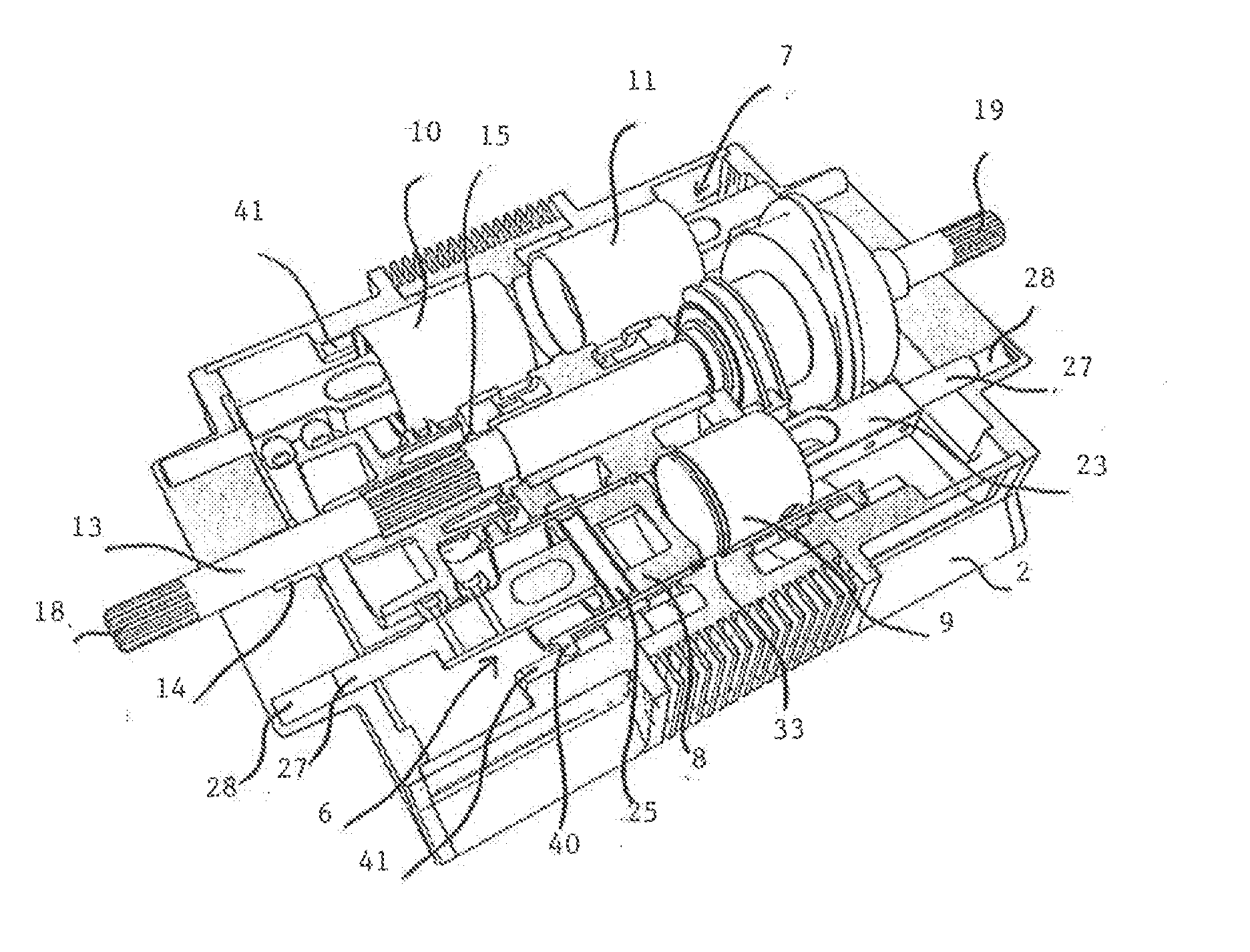
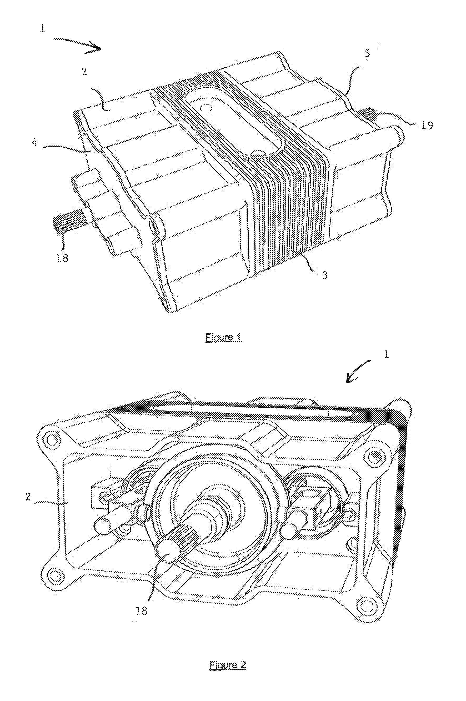
[0075]With reference to FIGS. 1 to 3, an engine 1 comprises a fixed cylinder block 2 which may be provided with conventional cooling fins 3. The cylinder block is attachable to a frame or vehicle chassis (not shown) using conventional fixing means. The cylinder block is provided with a pair of removable end caps or plates 4,5 attachable to the block with conventional fixing means to permit assembly and disassembly of the engine. The cylinder block may alternatively be formed in two halves attachable by conventional fixing means.

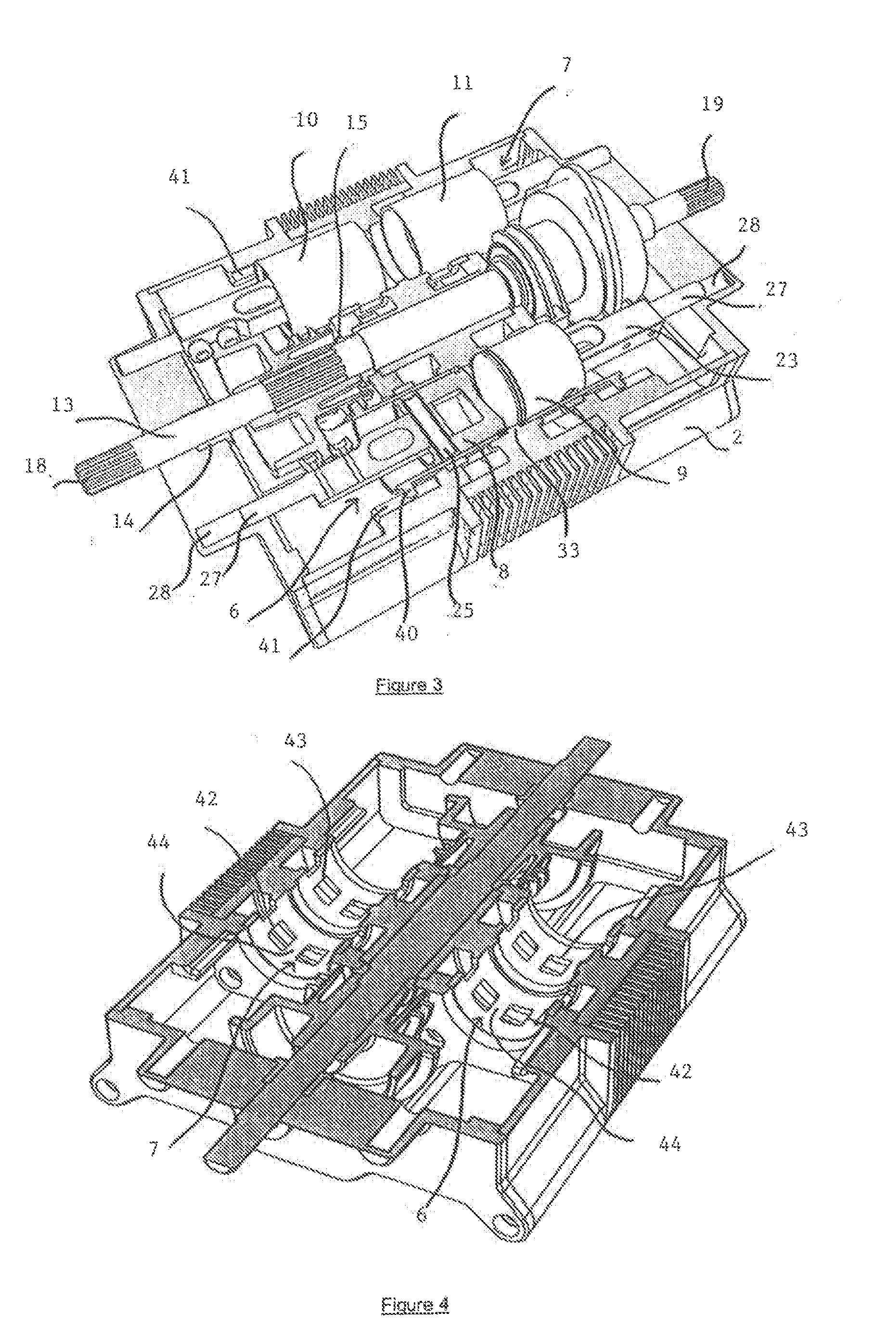
[0076]With reference to FIGS. 3 to 9, the cylinder block defines two elongate, horizontally extending, cylinders 6,7. A pair of opposed pistons 8,9 and 10,11 is arranged to be reciprocated linearly and coaxially within each of the cylinders 6,7 between respective Top Dead Centre (TDC) positions (FIG. 8) in which the piston crowns of the opposed pistons in each cylinder are substantially adjacent one another and respective Bottom Dead Centre (BDC) positions (F...


PUM


Abstract

The invention relates to an opposed piston engine comprising at least one cylinder, at least two pistons arranged to be reciprocated within the same cylinder in an opposed manner, at least one intake port through the cylinder wall, at least one exhaust port through the cylinder wall, at least one shaft arranged to be rotated by reciprocal motion of the opposed pistons, at least one reciprocatable sleeve valve within the cylinder for controlling porting of one or both of the at least one intake port and the at least one exhaust port, a sleeve valve driving mechanism for controlling reciprocal motion of the at least one sleeve valve, and a dwell mechanism. The dwell mechanism is configured to induce at least one period of dwell of the at least two pistons during their respective cycles of piston motion.

Description

FIELD OF THE INVENTION[0001]This invention relates to an internal combustion engine of the type in which a pair of opposed pistons is arranged to reciprocate within the same cylinder.[0002]The invention is particularly suited to an internal combustion engine operating a two-stroke cycle. It is also particularly suited to a two-stroke compression ignition engine.BACKGROUND TO THE PRESENT INVENTION[0003]Published UK patent application number GB2477272 and published international patent application number WO2011 / 092501 disclose an engine having a pair of pistons linked by a linking element which reciprocate within cylinders formed in a rotating cylinder block. As the pistons reciprocate within the cylinders, followers attached to the pistons cause the cylinder block to rotate around cams formed on a fixed central camshaft. The rotating cylinder block rotates within a fixed outer casing and is coupled to a further shaft for power take-off. A reciprocating sleeve valve is provided for ea...

Claims


Application Information

Patent Timeline
Patent Type & Authority Applications(United States)
IPC IPC(8): F02B75/28F01L1/04F01L5/04F01L5/20F02B9/02
CPCF02B75/282F02B9/02F01L1/04F01L5/20F01L5/04F01B2009/061F01L17/00F01B7/02F01B9/06F02B75/28F01L2820/031F01B3/045F02B75/26
Inventor ELLIS, PAUL
Owner TWO STROKE DEV
Why Eureka
Try Eureka