
System and method for fluorescence tomography

a fluorescence tomography and system technology, applied in tomography, diagnostics, application, etc., can solve problems such as confusion in image reconstruction

Inactive Publication Date: 2016-02-11
BOARD OF RGT THE UNIV OF TEXAS SYST
View PDF4 Cites 10 Cited by
  • Summary
  • Abstract
  • Description
  • Claims
  • Application Information

AI Technical Summary

Benefits of technology

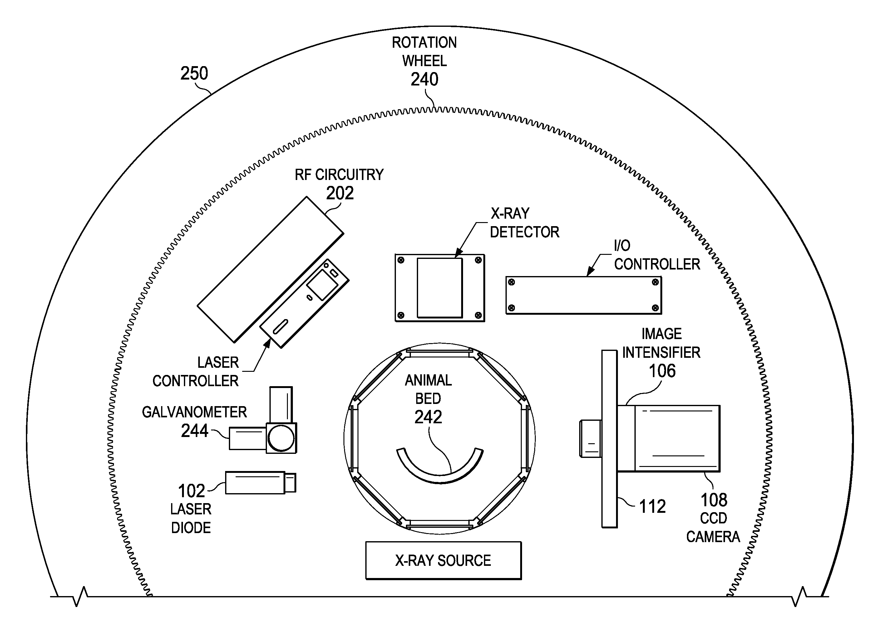
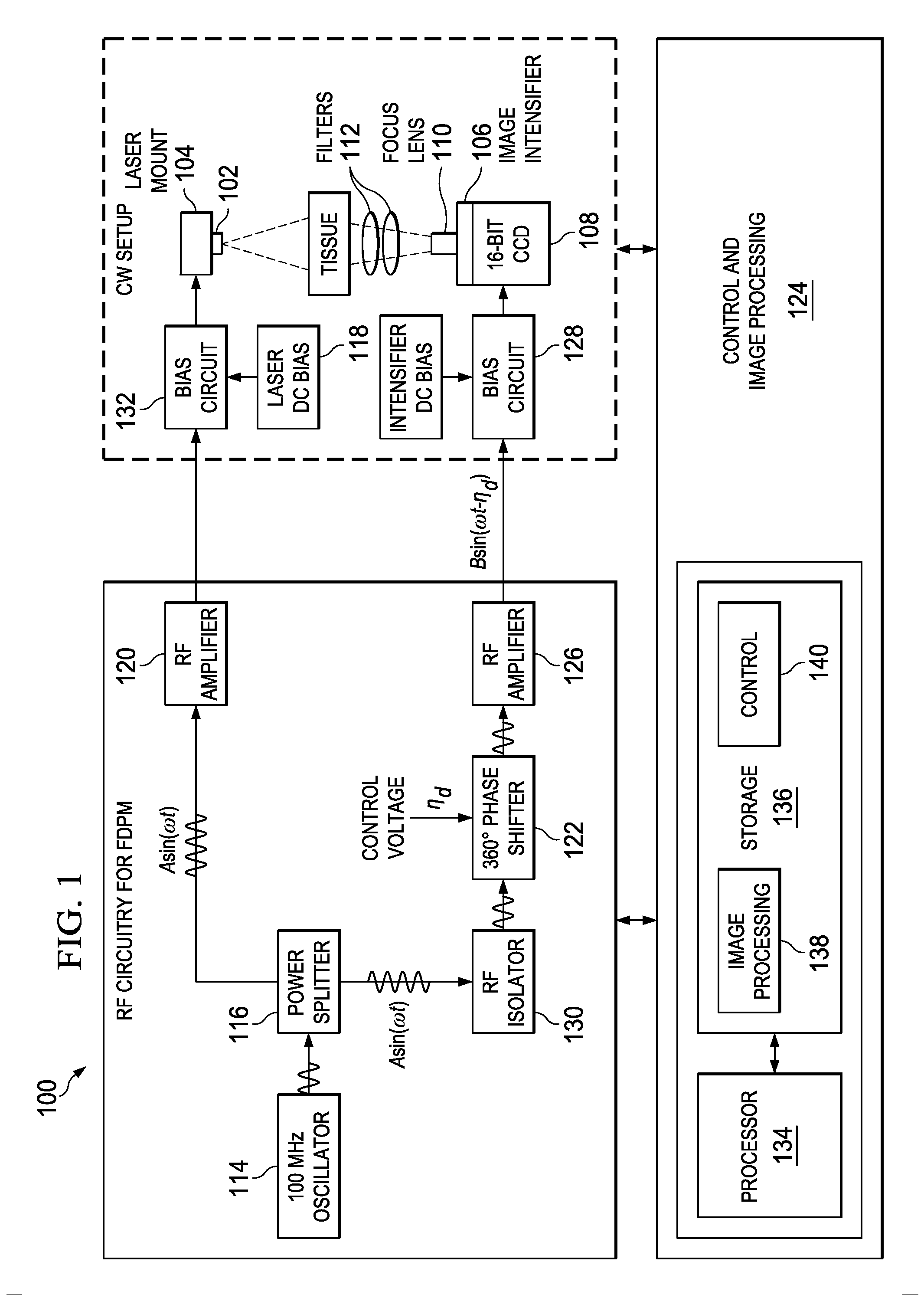
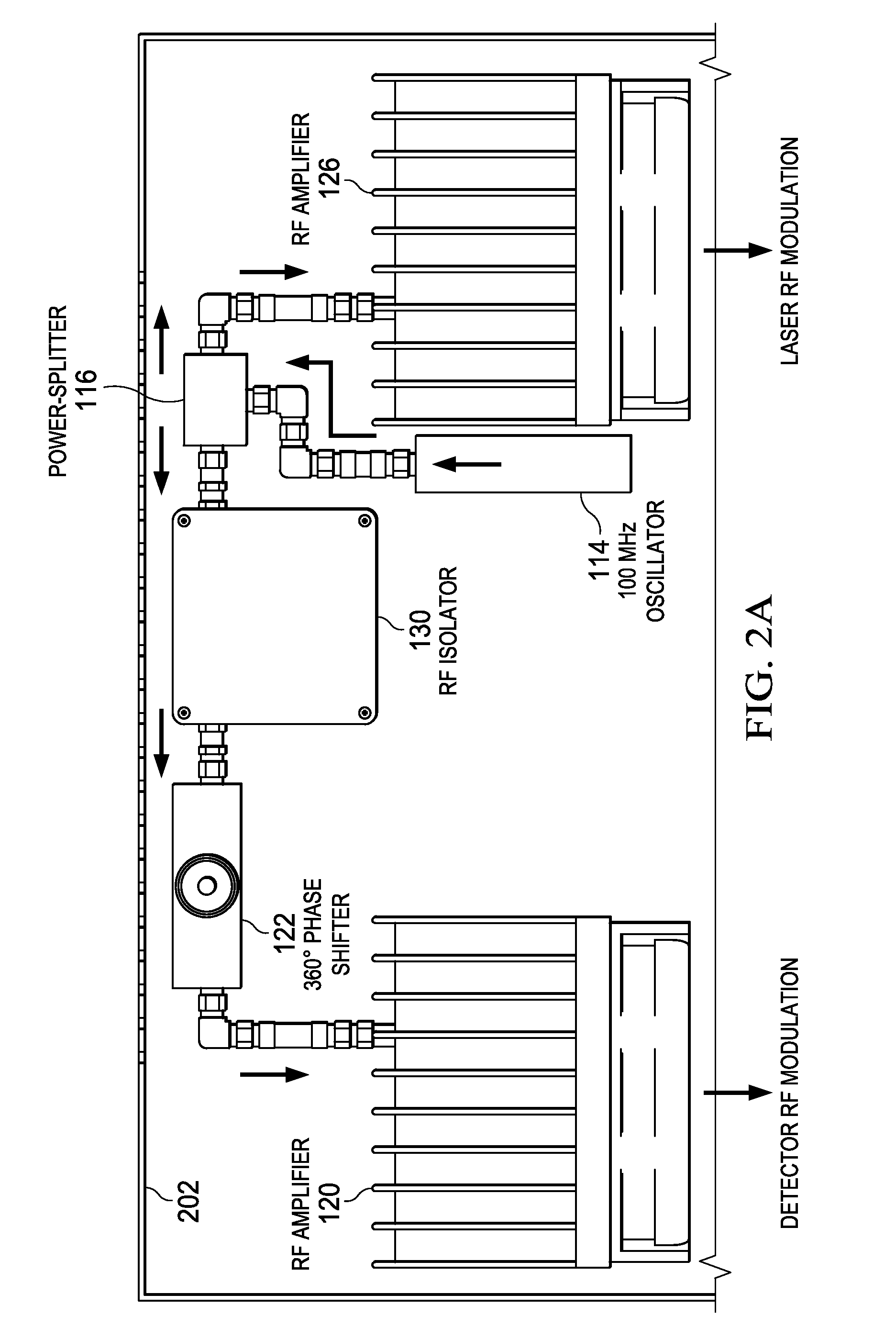
The patent describes an optical tomography system that uses near-infrared fluorescence imaging for medical imaging. The system includes a bed, a light source, and an image detector. The light source is attached to a wheel that rotates around the bed, and the image detector is positioned close to the bed. The system also includes a radio frequency (RF) circuitry that modulates the light source and demodulates the image signals captured by the detector. The system can generate a transformation matrix that aligns the captured fluorescence data with the surface of an object being imaged, and a computerized tomography (CT) scan of the object can be used to define the boundary surface of the object. The system can also use frequency domain photon migration (FDPM) and continuous wave (CW) measurements for imaging. The technical effects of the patent include improved accuracy and resolution in medical imaging, as well as improved optical tomography system design and operation.

Problems solved by technology

However for time-independent fluorescence and bioluminescence techniques, heterogeneous optical properties associated with different tissue structures and organs can attenuate light, confounding image reconstruction.

Method used


Image

  • System and method for fluorescence tomography
  • System and method for fluorescence tomography
  • System and method for fluorescence tomography

Examples


Embodiment Construction

[0030]The following discussion is directed to various embodiments of the invention. Although one or more of these embodiments may be preferred, the embodiments disclosed should not be interpreted, or otherwise used, as limiting the scope of the disclosure, including the claims. In addition, one skilled in the art will understand that the following description has broad application, and the discussion of any embodiment is meant only to be exemplary of that embodiment, and not intended to intimate that the scope of the disclosure, including the claims, is limited to that embodiment.

[0031]Instrumentation for different imaging techniques such as computed tomography (CT), positron emission tomography (PET), single-photon emission computed tomography (SPECT), and near-infrared fluorescence (NIRF) can be efficiently designed and operated to work as stand-alone modalities. Suitable co-registration approaches, such as use of fiducial markers, may be used to co-register the data acquired from...


PUM


Abstract

Systems and methods for near-infrared fluorescence (NIRF) imaging and frequency-domain photon migration (FDPM) measurements. An optical tomography system includes a bed, a wheel, a light source, an image detector, and radio frequency (RF) circuitry. The bed is configured to support an object to be imaged. The wheel is configured to rotate about the bed. The light source is coupled to the wheel. The image detector is coupled to the wheel and disposed to capture images of the object. The RF circuitry is coupled to the light source and the image detector. The RF circuitry is configured to simultaneously generate a modulation signal to modulate the light source, and generate a demodulation signal to modulate a gain of the image detector.

Description

CROSS REFERENCE TO RELATED APPLICATIONS[0001]This application is a 35 U.S.C. §371 national stage application of PCT / US2014 / 030264 filed Mar. 17, 2014, and entitled “System and Method for Fluorescence Tomography,” which claims benefit of provisional application Ser. No. 61 / 787,660, filed on Mar. 15, 2013, entitled “System and Method for Fluorescence Tomography,” each of which is hereby incorporated herein by reference in its entirety.STATEMENT REGARDING FEDERALLY SPONSORED RESEARCH OR DEVELOPMENT[0002]This invention was made with U.S. Government support under CA135673 awarded by the National Institutes of Health. The government has certain rights in the invention.BACKGROUND[0003]Hybrid tomography systems that provide anatomical information through computed tomography (CT) or magnetic resonance (MR) and molecular biochemical information through positron emission tomography (PET) or single-photon emission computed tomography (SPECT) can accelerate pre-clinical discovery by offering fea...

Claims


Application Information

Patent Timeline
IPC IPC(8): A61B5/00A61B6/00A61B6/03A61B6/04A61G13/10
CPCA61B5/0073A61B5/0071A61B6/032A61B2562/0242A61B6/583A61G13/10A61B6/0407A61B5/4869
Inventor DARNE, CHINMAYLU, YUJIETAN, I-CHIHZHU, BANGHESEVICK-MURACA, EVA
Owner BOARD OF RGT THE UNIV OF TEXAS SYST
Learn More