This helps you quickly interpret patents by identifying the three key elements:
Problems solved by technology
Method used
Benefits of technology
Benefits of technology
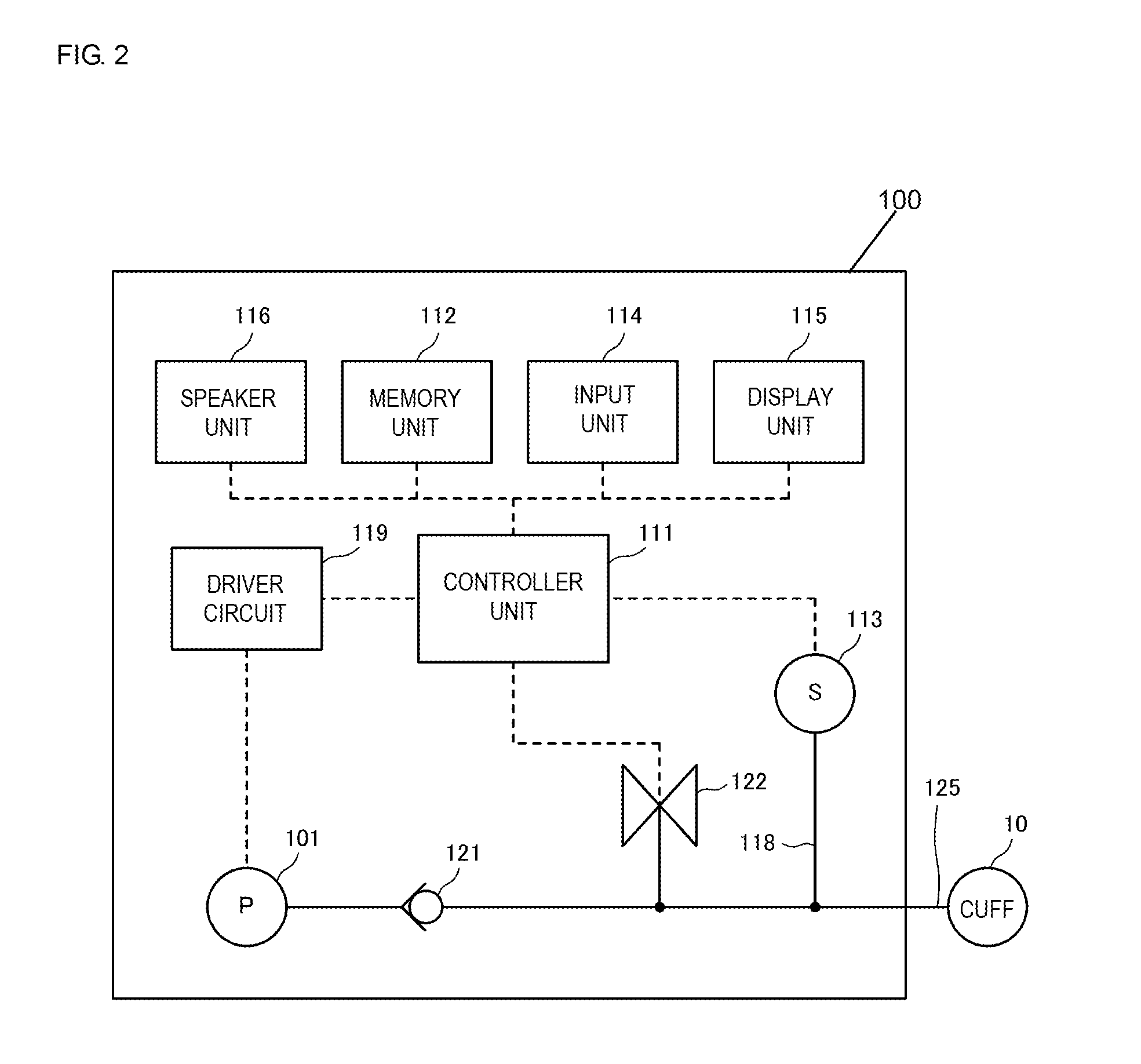
The patent proposes the use of an active control valve to regulate the flow of gas to a cuff, instead of a flow volume regulator valve. This would allow for more precise control of the gas flow and reduce the need for high-speed driving. The patent aims to achieve downsizing, lower manufacturing costs, lower electric power consumption, and quieter operation of the device.
Problems solved by technology
However, when the flow volume remains small, it takes time to inflate the cuff for the first time.
This requires the adjustment of the throttle valve and the like each time the cuff is inflated, and causes a problem of decreasing work efficiency.
Method used
Image
Click on the blue label to locate the original text in one second.
Reading with bidirectional positioning of images and text.
Examples
first embodiment
of the Present Disclosure
[0069]A cuff pressure controller device 100 according to the first embodiment of the present disclosure is now described below.
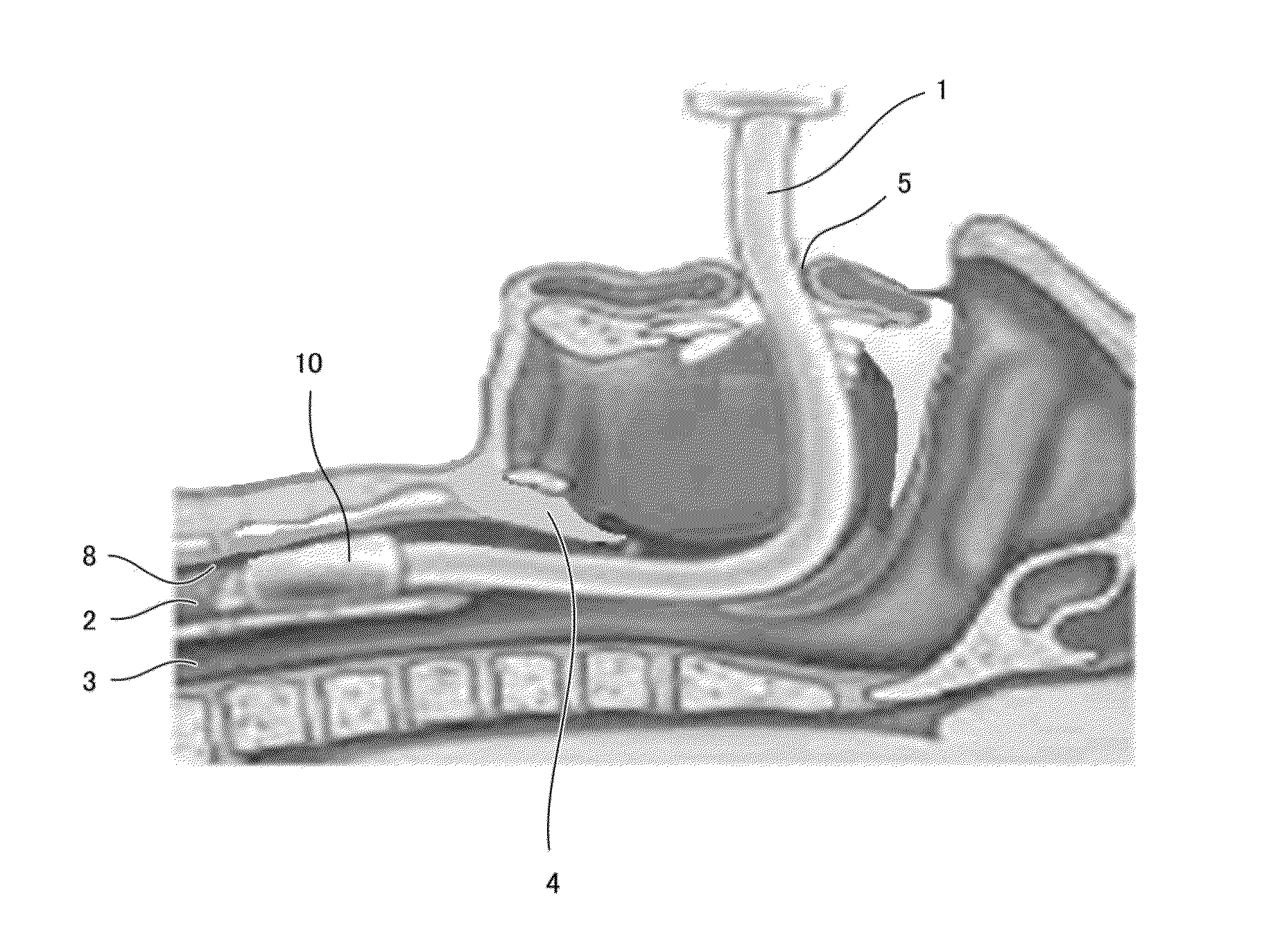
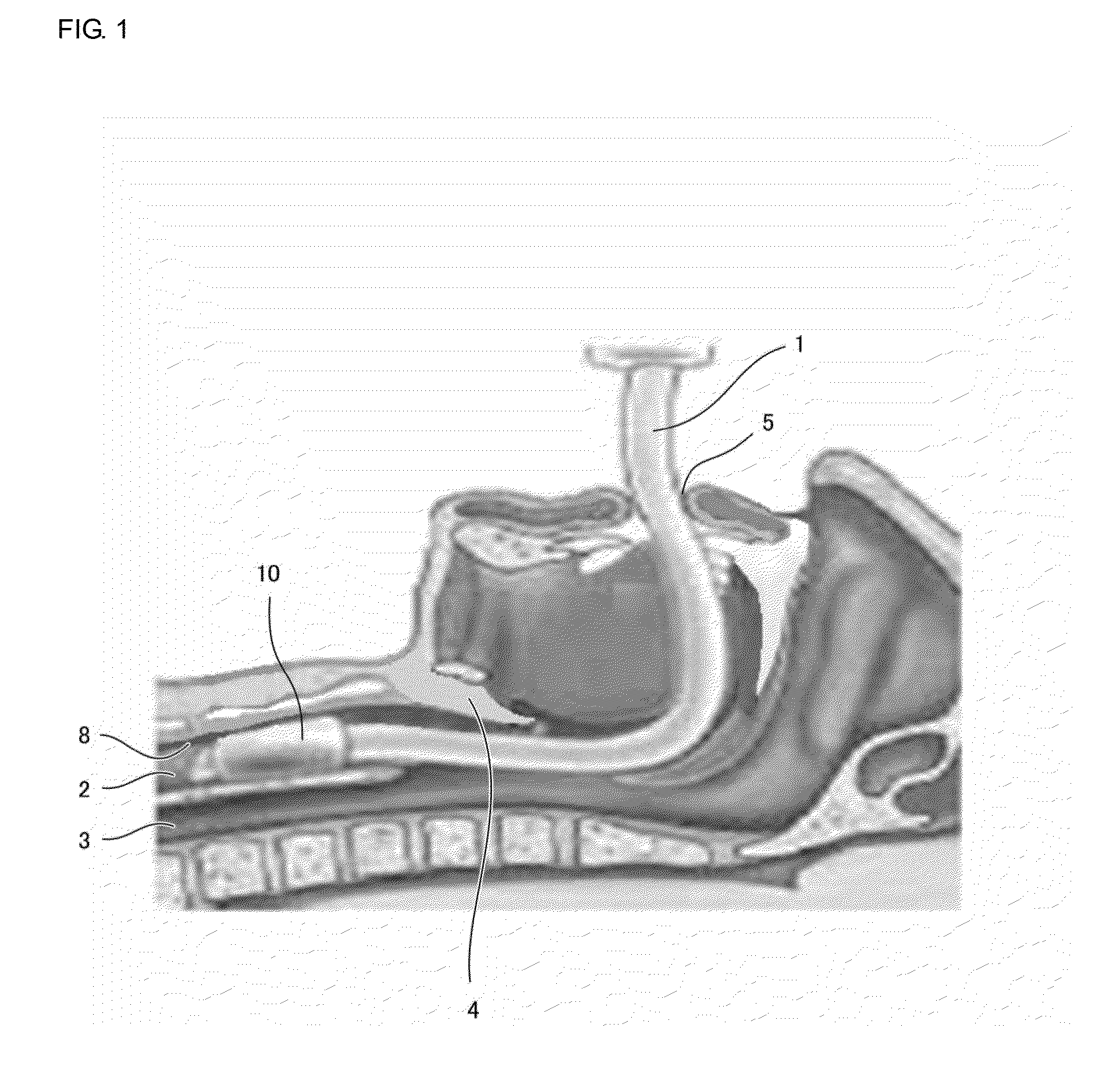
[0070]FIG. 1 is a schematic diagram depicting how an intubation tube is inserted into trachea through cavity of mouth.
[0071]In the case where tracheal intubation is performed to secure airway during the usage of artificial ventilators, when there is a gap between an intubation tube 1 inserted through cavity of mouth 5 and an inner wall 8 of trachea 2, secretions from esophagus 3 such as gastric fluid, saliva, and the like enters trachea 2, causing a subject to be at a high risk of developing ventilator-associated pneumonia (hereinafter, referred to as “VAP”). Particularly, during the tracheal intubation, epiglottis 4 is kept open, and gastric fluid from esophagus 3 is likely to enter trachea 2.
[0072]To block such secretion inflow, a cuff 10 is provided at a predetermined location of an outer periphery of the intubation tube 1. This c...
second embodiment
of the Present Disclosure
[0116]A cuff pressure controller device 100 according to the second embodiment of the present disclosure is now described below.
[0117]The cuff pressure controller device of the second embodiment differs from the cuff pressure controller device 100 of the first embodiment in having a piezoelectric pump 201 instead of the piezoelectric pump 101. The remaining configuration is the same as that of the first embodiment. Thus, the redundant description is omitted.
[0118]The structure of the piezoelectric pump 201 is described in detail with reference to FIG. 7 and FIG. 8.
[0119]FIG. 7 is an exploded perspective view of the piezoelectric pump 201 according to the second embodiment of the present disclosure. FIG. 8 is a cross-sectional diagram of relevant part of the piezoelectric pump 201 depicted in FIG. 7.
[0120]A substrate 291, a flexible plate 251, a spacer 253A, a reinforcing plate 243, a vibration plate unit 260, a piezoelectric element 242, a spacer 253B, an el...
BACKGROUND OF THE DISCLOSURE[0001]1. Field of the Disclosure[0002]The present disclosure relates to cuff pressure controller devices that control the pressure inside the cuff.[0003]2. Description of the Related Art[0004]In related art, tracheal intubation is well known in medical fields relating to artificial ventilators. In tracheal intubation, a technician such as a medical doctor and the like inserts an intubation tube into trachea of a subject (usually, a human body) from the cavity of mouth or nose to maintain an open airway, and oxygen is sent to lungs via the intubation tube.[0005]When there is a gap between the intubation tube and the inner wall of trachea, secretions such as gastric fluid, saliva, and the like enters trachea, and the subject may be at a high risk of developing ventilator-associated pneumonia (hereinafter, referred to as “VAP”). To block such secretion inflow, a cuff is provided at the outer wall of the intubation tube.[0006]The cuff inflates upon receiving ...
Claims
Application Information
Patent Timeline
Application Date:The date an application was filed.
Publication Date:The date a patent or application was officially published.
First Publication Date:The earliest publication date of a patent with the same application number.
Issue Date:Publication date of the patent grant document.
PCT Entry Date:The Entry date of PCT National Phase.
Estimated Expiry Date:The statutory expiry date of a patent right according to the Patent Law, and it is the longest term of protection that the patent right can achieve without the termination of the patent right due to other reasons(Term extension factor has been taken into account ).
Invalid Date:Actual expiry date is based on effective date or publication date of legal transaction data of invalid patent.

