Method and apparatus for controlled alignment and deposition of branched electrospun fiber

a technology of electrospun fiber and branched fiber, which is applied in the direction of filament/thread forming, other domestic articles, coatings, etc., can solve the problems of jet branching and/or splitting, non-uniform deposition of fibers on the substrate, and further elongation of the jet, so as to avoid disturbance of the fiber flow, improve the arrangement of aligned cells, and quickly collect parallel fibers

Active Publication Date: 2016-02-18
UNIVERSITY OF CENTRAL OKLAHOMA
View PDF0 Cites 14 Cited by
  • Summary
  • Abstract
  • Description
  • Claims
  • Application Information

AI Technical Summary

Benefits of technology

[0010]Micron to nano size fibers can be applied to a variety of substrates across a range of applications to enable or enhance desired performance. For example, when nano size fibers are fused with biomedical implants, osseointegration of an implant with the host tissue in orthopedics and orthodontics is improved. The effects of fibers on the interface fracture toughness of implant / cement specimens with and without fibers at the interface have not yet been known. Such studies are important for the design of a lasting implant for orthopedic applications. In one aspect, a specific goal of the present invention is to coat different orthopedic and orthodontic implants by aligned micron to nano-size fiber for the improvement of the bonding of the implant with the surrounding biomaterial in physiological conditions. In another aspect, the present invention can also be applied to catalysis, filtration media, filler for fiber-containing composites, and scaffolds for tissue engineering. Alignment of the electrospun fibers will increase the number of applications for which the fibers are suited, including for example, optical polarizers and bone scaffold matrix.
[0012]In accordance with certain embodiments of the present disclosure, a method and apparatus is provided to control the deposition of electrospun fiber width and alignment. The method includes significant modifications of current methods of electrospinning used to deposit micro fiber and nanofiber onto a substrate. Current methods and apparatus for electrospinning typically comprise four parts: syringe pump to control flow rate, syringe with a needle which act as one of the electrodes to charge the polymer solution, high-voltage power supply to generate electric field, and collector with substrate which acts as an electrode to collect fibers as illustrated in FIG. 1 (Khandaker, M., K. C. Utsaha and T. Morris (2014). “Interfacial fracture toughness of titanium-cement interfaces: Effects of fibers and loading angles.”International Journal of Nanomedicine 9(1)). A polymer solution, sol-gel, particulate suspension or melt is loaded into the syringe and this liquid is extruded from the needle tip at a constant rate by a syringe pump. The collector is usually a charged parallel plate structure or some form of disk rotating in a plane perpendicular to the longitudinal axis of the syringe needle. Unlike current methods, the present invention can be used for not only non-woven polymer fabric or weaving polymer fibers into a fabric, but also on round, flat, and irregular (like hip implant, orthopedic screws) shape collectors. The present invention may also be used for metal coating with a controlled aligned fiber on these collectors. The present invention is configurable with multiple disks that provide a capability to adjust the length of spun fibers applied to a substrate, enabling parallel deposition of fibers across a range of substrate physical dimensions.
[0014]Fiber directed towards the circumference of the primary collector shape may be utilized to deposit fiber on a relatively round or on flat substrates and other more irregular shapes (like hip implant shape or electrical substrates) that may be mounted on the primary collector shaft (as illustrated in FIG. 4). The primary collector shaft (as illustrated in FIG. 2) is set spinning by a DC motor and positioned to intercept an outer band fiber branches in the electromagnetic field, which coats the collector with aligned fiber. The position of the collector shape may be altered to move the axis of rotation toward or away from the fibers aligned with the electromagnetic field. The position of the needle may be adjusted using a non-conducting support (e.g., wooden or plastic bar) attached with the tube of the syringe to increase or decrease the distance between the needle tip and the edge of the metallic disk (as illustrated in FIG. 3). The needle, primary and auxiliary disk components can be mounted in a sealable chamber to avoid disturbance of the fiber flow due to the air flow from the room to the chamber. Using the present invention, an uninterrupted direct application of aligned fibers can be applied to a variety of target samples. The target samples may be any of a plurality of shapes, including those typical of biomedical implants, biomaterial interfaces and tissue engineering scaffolds. The insulating washers, fastener (e.g., bolt head) and primary collector shape (e.g., specimen holder) of the present invention are adaptable to achieve different coating topography (fiber diameter, distance between two fiber, coating thickness) on the target (e.g., an implant) surface. Research by the named inventors has shown (discussed in example section) that the applied coating of aligned fiber on an implant can induce and improve aligned cell arrangements, including elongated unidirectional cell alignment and the strength between implant / biomaterial interfaces. Further, the present invention is confirmed to enable control of the deposition of the branches of the fibers to provide uniform distribution of the fiber on the substrate.
[0015]In another embodiment, the present invention provides a dual disk method that incorporates the advantages of the electric field of the single disk method. The present invention is reconfigurable between a single disk and a multiple disk arrangement. Significant benefits of the two disk configuration are the ability to control the length of each fiber, rapidly collect parallel fibers of the same length, and the capability of single fiber collection. This is done similarly to the single disk collection method, but instead of attracting the fibers to the center the fibers are forced to the sharp edge of the disk. This is accomplished by taking advantage of the electromagnetic field of a thin solid disk near the edge. The field lines of a point charge both positive and negative produce the path of strongest attraction. The two rotating disks take advantage of the natural oscillation of the nanofiber, and in a manner similar to the parallel plate collection method. Giving the negatively charged disks the ability to rotate and tilt produces cross-linking (stray fibers) and the arcing effect of static charge respectfully. The fibers are allowed to follow random trajectories until they encounter the electro-magnetic field of a first disk. At that point the fibers align back and forth along a plane that intersects both the first disk and a second disk. Separation between the fiber threads is controlled by adjusting rotation speed of the first disk and the second disk. As disk rotation speed is increased, separation between attached fibers is decreased. The disks are mirrored and adjusted to the desired length, with both disks being negatively charged. Due to the fibers grounding out on the disk and sharing the same charge, along with the effects of the electro-magnetic field, there is an arcing effect. This effect is adjusted in shape by introducing a slight angle to both disks in opposite directions so the tops of the blades are closer together and the bottom of the disks are slightly further apart. Then by spinning the blades the fibers are pulled tight and one can collect the fibers with greater control. (See FIGS. 5A through 5D.)

Problems solved by technology

If not controlled, the branches of the fibers create a non-uniform deposition on the substrate.
Growth of electrical bending instability (also known as whipping instability) and further elongation of the jet may be accompanied with the jet branching and / or splitting.
Such branching produces non-uniform deposition of fiber on the collector during the electrospin process.
A method and apparatus to separate out a continuous single thread of fiber from many fiber branches has not been solved.

Method used


Image

  • Method and apparatus for controlled alignment and deposition of branched electrospun fiber
  • Method and apparatus for controlled alignment and deposition of branched electrospun fiber
  • Method and apparatus for controlled alignment and deposition of branched electrospun fiber

Examples


Embodiment Construction

[0030]In brief:

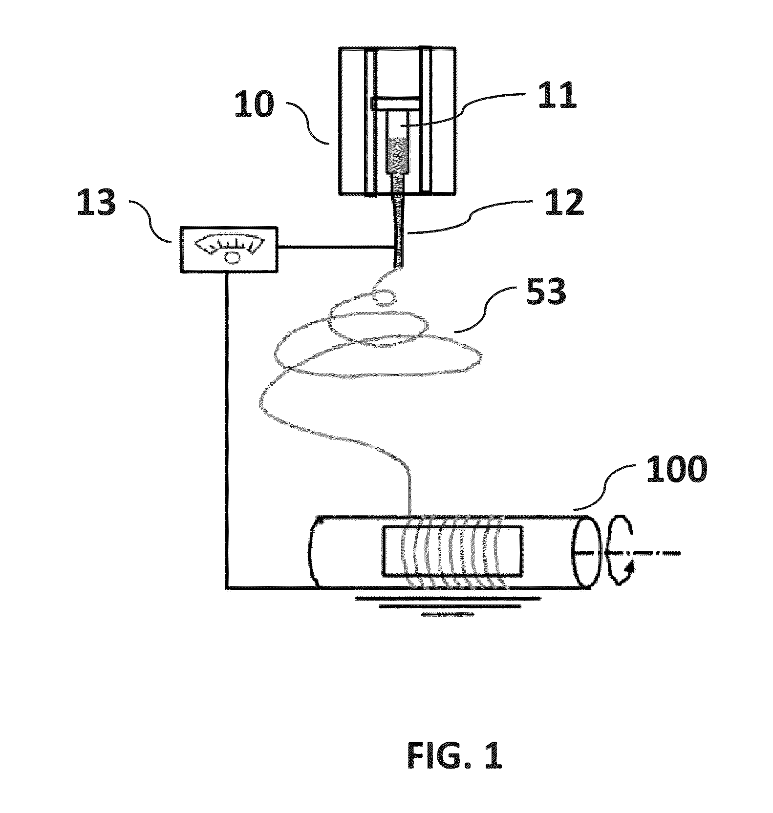
[0031]FIG. 1 is a non-limiting diagram schematically illustrating the method of the typical electrospin process. A typical electrospin setup consists of syringe pump, syringe with a needle, high-voltage power supply, and collector. Presently a single rotating or flat target disk, a pair of charged collector strips have been used as the fiber collector.

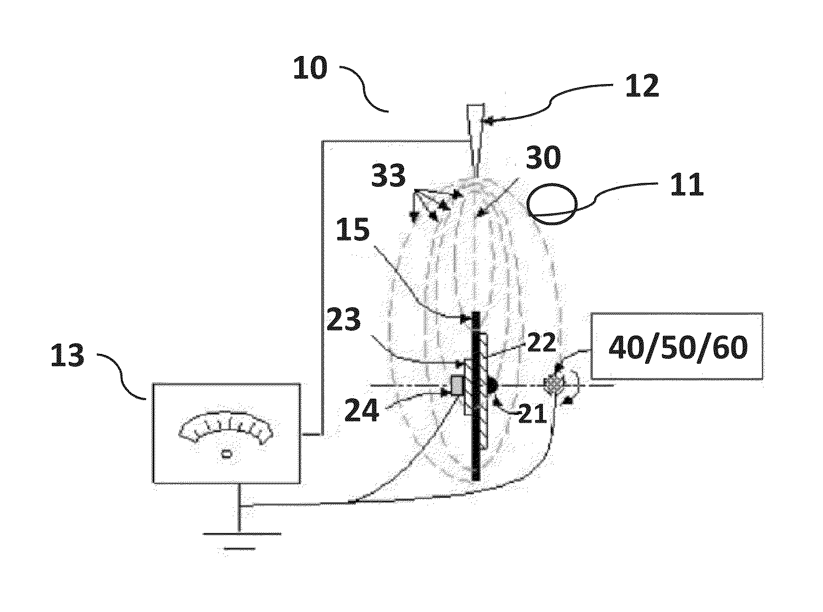
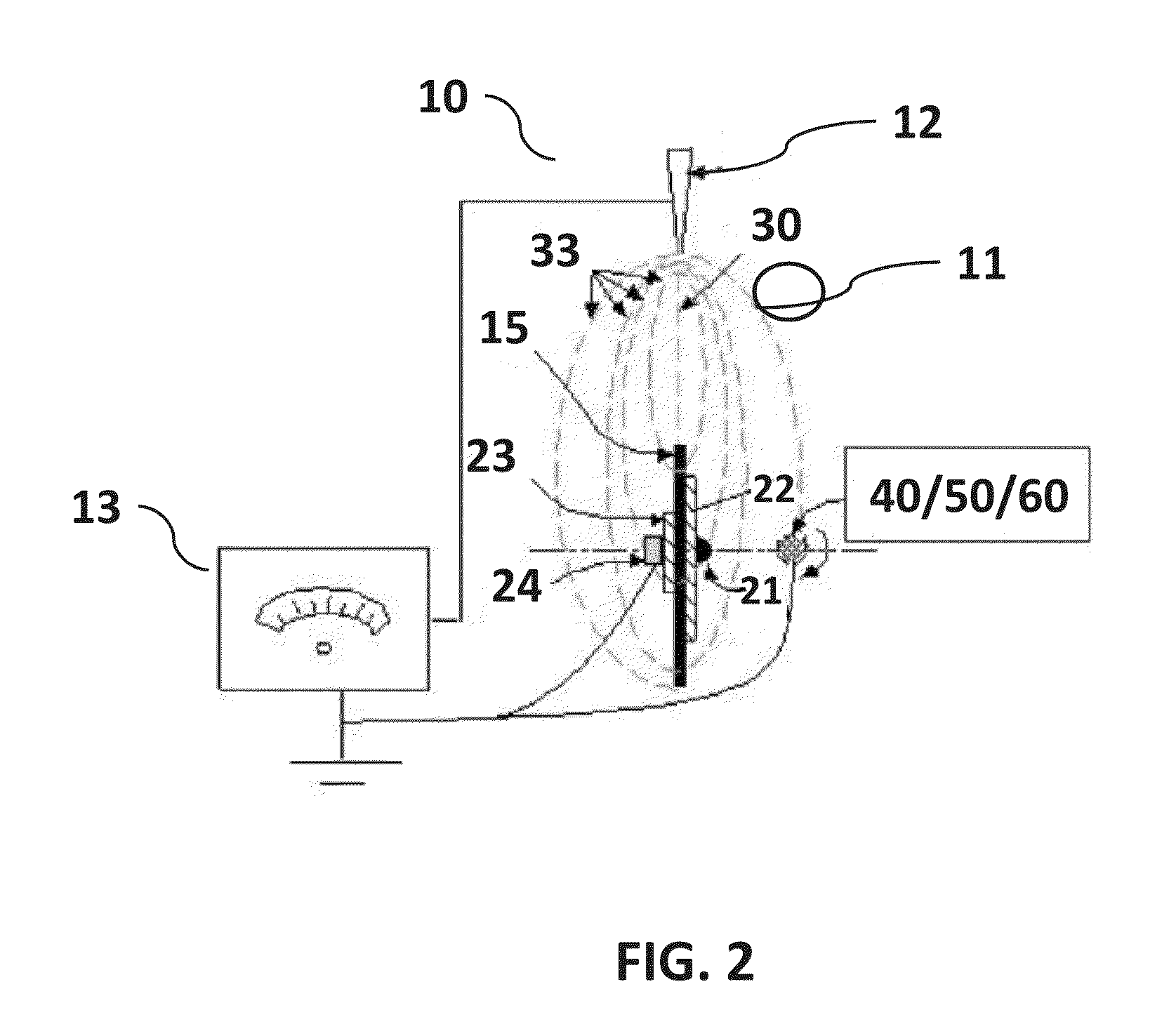
[0032]FIG. 2 is a non-limiting diagram schematically illustrating the method of the present invention. The embodiment shown in the diagram uses the path of the electromagnetic field generated by the potential difference between charged needle and rotating auxiliary metallic disk using a high-power voltage source to capture, deposit and align fiber on a substrate. The apparatus shown includes the syringe needle, DC motor, blunt bolt, and front insulating washer. A linear stage is used to move the collector back and forth.

[0033]FIG. 3 is a non-limiting diagram illustrating the components of the apparatus of the present inv...


PUM

PropertyMeasurementUnit
diameter×1aaaaaaaaaa
strain rateaaaaaaaaaa
electromagnetic fieldaaaaaaaaaa

Abstract

A method for separating out nano-scale fiber threads from many fiber branches and controlling alignment and deposition of the fiber threads on a substrate, comprising: electrospinning at least synthetic polymer fiber streams from an electrically charged syringe needle; controlling the fiber using at least one electrically charged metallic disk rotating about an axis positioned below the needle; capturing the fiber using electrically grounded collector; extracting a single or plurality of fiber branch threads from the fiber streams, wherein the single or plurality of fiber branch threads is attracted to and intercepted by the collector shape, and depositing the single or plurality of fiber branch threads as substantially aligned fiber on the collector.

Description

CROSS REFERENCES TO RELATED APPLICATIONS[0001]This application is a continuation-in-part of U.S. patent application Ser. No. 14 / 734,147 filed Jun. 9, 2015 by the University of Central Oklahoma (Applicant), entitled “Method and apparatus for controlled alignment and deposition of branched electrospun fiber” the entire disclosure of which is incorporated herein by reference in its entirety for all purposes. This application also claims the benefit of U.S. Provisional Patent Application No. 62 / 038,506 filed on Aug. 18, 2014 in the name of Morshed Khandaker and William Paul Snow, which is expressly incorporated herein by reference in its entirety.STATEMENT AS TO RIGHTS TO INVENTIONS MADE UNDER FEDERALLY SPONSORED RESEARCH OR DEVELOPMENT[0002]This invention was made with Government support of OK-INBRE (Oklahoma IDeA Network of Biomedical Research Excellence). The OK-INBRE is a grant from the National Institute of General Medical Sciences of the National Institutes of Health through Grant...

Claims


Application Information

Patent Timeline
Patent Type & Authority Applications(United States)
IPC IPC(8): D01D5/00
CPCD01D5/0069D01D5/0076D01D5/0092D01D5/0084
Inventor KHANDAKER, MORSHEDSNOW, WILLIAM PAUL
Owner UNIVERSITY OF CENTRAL OKLAHOMA
Why Eureka
Try Eureka