Silicon carbide multilayered cladding and nuclear reactor fuel element for use in water-cooled nuclear power reactors

a technology of silicon carbide and nuclear power reactor, which is applied in the direction of distance measurement, greenhouse gas reduction, instruments, etc., can solve the problems of increasing the risk of fission gas release during long-term operation, increasing the risk of fission gas release, and reducing the safety margin. , to achieve the effect of reducing corrosion

Inactive Publication Date: 2016-02-18
CERAMIC TUBULAR PRODS
View PDF4 Cites 34 Cited by
  • Summary
  • Abstract
  • Description
  • Claims
  • Application Information

AI Technical Summary

Benefits of technology

[0020]The cladding tube may further include an outer monolith layer for reducing corrosion during reactor operation. In one embodiment, the outer monolith layer is high density silicon carbide formed by a process selected from the group consisting of chemical vapor infiltration and chemical vapor deposition. Also, the outer monolith layer may have a thickness between about 3 and about 10 mils.

Problems solved by technology

However, because the silicon carbide clad has a ceramic structure that is not susceptible to mechanical creep during operation, its behavior when operating with uranium oxide fuel leaves an insulating gap between the cladding and the uranium oxide fuel, leading to higher fuel temperatures and eventually to more fission gas release during long-term operation.
The higher fuel centerline temperatures with silicon carbide cladding as compared to zircaloy cladding, may lead to reduced margin to fuel element melting during nuclear power plant transients, which reduces the safety margin.

Method used


Image

  • Silicon carbide multilayered cladding and nuclear reactor fuel element for use in water-cooled nuclear power reactors
  • Silicon carbide multilayered cladding and nuclear reactor fuel element for use in water-cooled nuclear power reactors
  • Silicon carbide multilayered cladding and nuclear reactor fuel element for use in water-cooled nuclear power reactors

Examples


Embodiment Construction

[0035]In the following description, like reference characters designate like or corresponding parts throughout the several views. Also in the following description, it is to be understood that such terms as “forward,”“rearward,”“left,”“right,”“upwardly,”“downwardly,” and the like are words of convenience and are not to be construed as limiting terms.

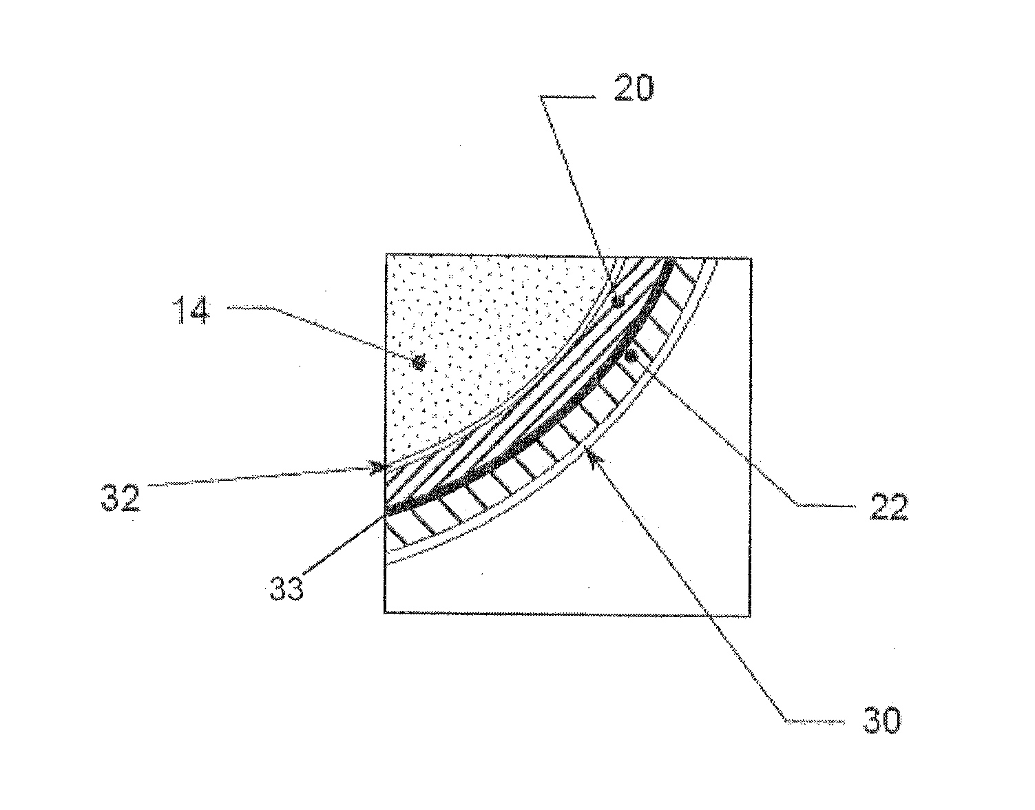
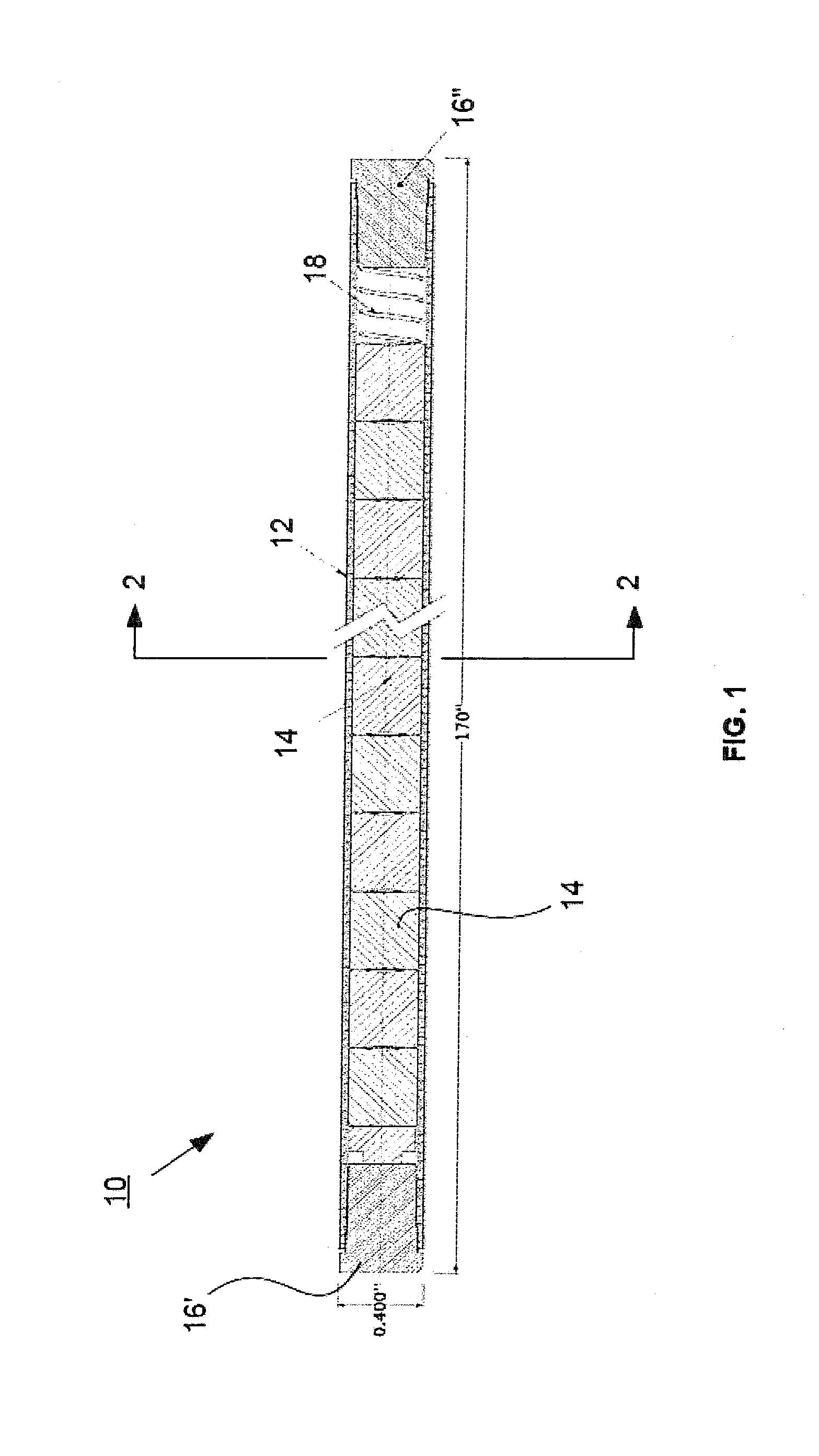
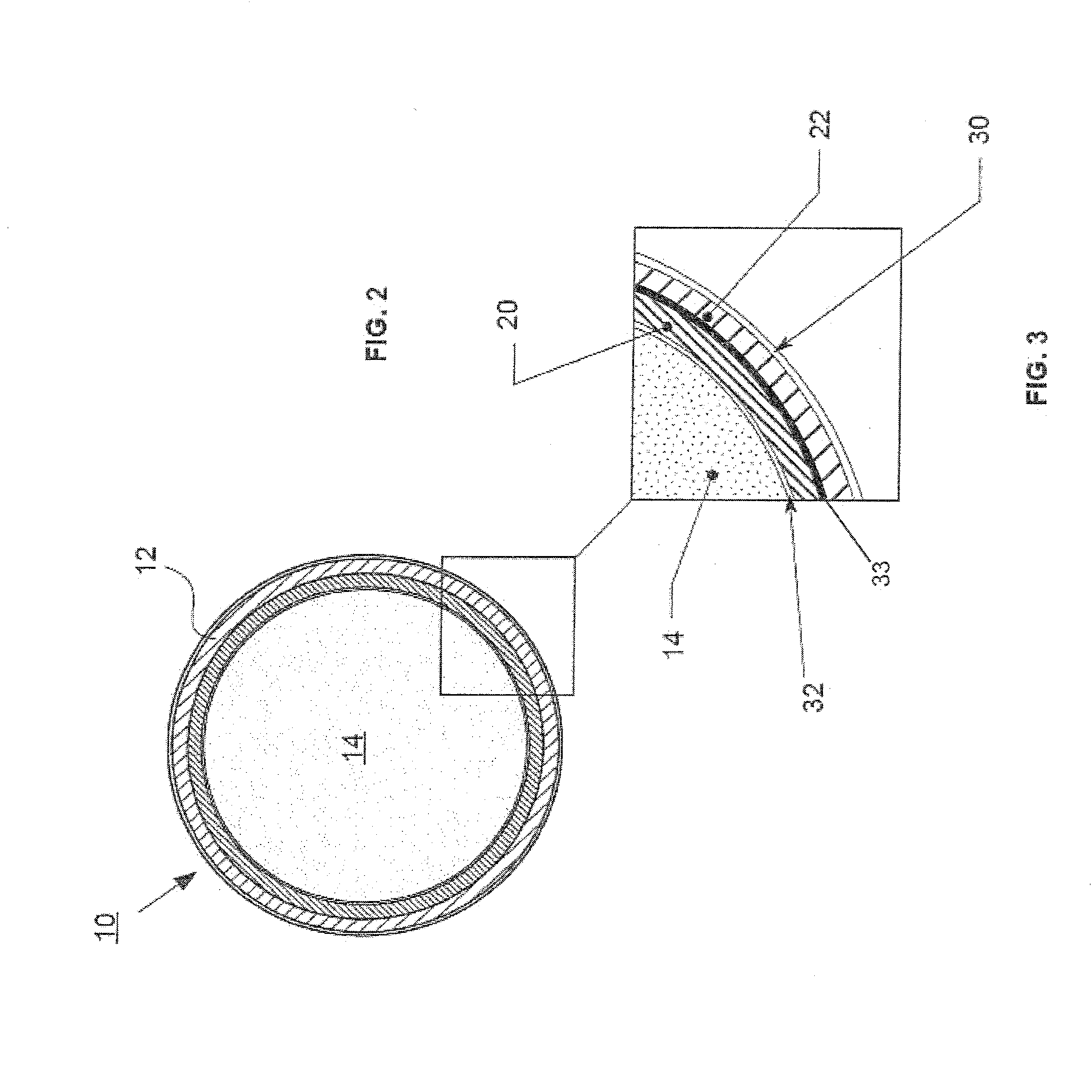
[0036]Referring now to the drawings in general and FIG. 1 in particular, it will be understood that the illustrations are for the purpose of describing a preferred embodiment of the inventions and are not intended to limit the inventions thereto. As best seen in FIG. 1, a nuclear fuel element, generally designated 10, is shown constructed according to the present inventions. FIG. 1 is a longitudinal, cross-sectional view of the SiC clad fissionable fuel element that is the subject of the present inventions.

[0037]As shown in FIG. 1, the fuel element 10 is a tubular structure, generally about 170 inches long and 0.4 inches diameter. Variat...


PUM

PropertyMeasurementUnit
diameteraaaaaaaaaa
thicknessaaaaaaaaaa
thicknessaaaaaaaaaa

Abstract

A nuclear fuel element for use in water-cooled nuclear power reactors and an improved multilayered silicon carbide tube for use in water-cooled nuclear power reactors and other high temperature, high strength thermal tubing applications including solar energy collectors. The fuel element includes a multilayered silicon carbide cladding tube. The multilayered silicon carbide cladding tube includes (i) an inner layer; (ii) a central layer; and (iii) a crack propagation prevention layer between the inner layer and the central layer. A stack of individual fissionable fuel pellets may be located within the cladding tube. In addition, a thermally conductive layer may be deposited within the cladding tube between the inner layer of the cladding tube and the stack of fuel pellets. The multilayered silicon carbide cladding tube may also be adapted for other high temperature, high strength thermal tubing applications including solar energy collectors.

Description

CROSS-REFERENCE TO RELATED APPLICATIONS[0001]This application is related to PCT Application No. 12 / 42981, filed Jun. 19, 2012, the contents of which are hereby incorporated by reference in its entirety. This application claims the benefit of Provisional Application Ser. No. 61 / 740,102 filed Dec. 12, 2012.STATEMENT AS TO RIGHTS TO INVENTIONS MADE UNDER FEDERALLY SPONSORED RESEARCH OR DEVELOPMENT[0002]Work described herein may have been supported in part by Department of Energy (DOE) Grant No. DE-SC0004225. The United States Government may therefore have certain rights in the inventions.BACKGROUND[0003]1. Field[0004]The present inventions relate generally to nuclear fuel elements for use in water-cooled nuclear power reactors and, more particularly, to an improved multilayered silicon carbide cladding tube including a crack propagation prevention layer, which may be adapted to receive a stack of a variety of individual fissionable fuel pellets or may also be adapted for other high tem...

Claims


Application Information

Patent Timeline
Patent Type & Authority Applications(United States)
IPC IPC(8): G21C3/07
CPCG21C3/07C04B35/51C04B2235/32C23C16/26C23C16/325C23C28/046G21C21/02Y02E30/30
Inventor FEINROTH, HERBERTALES, MATTHEW W.MARKHAM, GREGORY T.
Owner CERAMIC TUBULAR PRODS
Why Eureka
Try Eureka