Integrated gas discharge tube and preparation method therefor

Active Publication Date: 2016-02-18
SHENZHEN BENCENT ELECTRONICS CO LTD
View PDF1 Cites 5 Cited by
  • Summary
  • Abstract
  • Description
  • Claims
  • Application Information

AI Technical Summary

Benefits of technology

[0046]Unlike in the prior art, the structure of the integrated gas discharge tube in the present disclosure is designed to include an upper cover and an insulative base, and electrodes are disposed at each of the inner and outer surfaces of the insulative base, so that the discharge effect of the g

Problems solved by technology

The gas discharge tube with the traditional structure has a poor discharge effect, and is disadvantageous in manufacturing for its complicated structure.
the raw material used for manufacturing the traditional gas discharge tube need be processed in many steps, and therefore causes a high cost;
the metallized ceramic insulative tube is twice subjected to the high-temperature sintering at 1000° or higher, and the solders are subjected to the high-temperature smelting at 1000° or higher, so that the energy consumption for the raw materials is high; in addition, the resultant product is obtained

Method used


Image

  • Integrated gas discharge tube and preparation method therefor
  • Integrated gas discharge tube and preparation method therefor
  • Integrated gas discharge tube and preparation method therefor

Examples


third embodiment

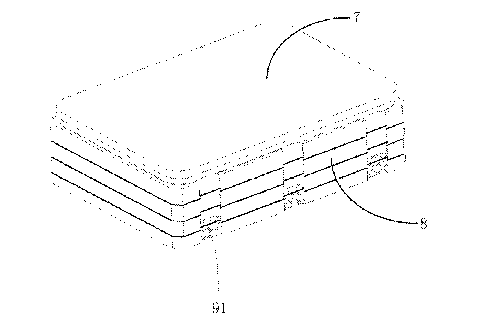
[0074]In a third embodiment, the insulative base 8 has an integral structure (not shown), and includes a bottom, a cavity body and a solder layer which are integrally formed, where the bottom is integrated with a plurality of discharge electrodes, the solder layer is on the cavity body, and the cavity body is provided with at least one conductive strip (which is in a semi-cylindrical shape, for example) extending in a vertical direction and / or a transverse direction. The conductive upper cover 7 is sealed on the solder layer to form a sealed cavity, which is configured to receive inert gas.

[0075]In a variant of the embodiment, at least one electrode on the outer surface of the bottom of the insulative base extends to a side wall of the insulative base. For example, as shown in FIG. 3 or 5, the part of the electrode that extends to the side wall of the insulative base is represented by a shadow structure 91 at the lateral side of the insulative base 8. In the present embodiment, the ...

fourth embodiment

[0076]In a fourth embodiment, the insulative base 8 has an integral structure (not shown), and includes a bottom, a cavity structure, a solder layer and a metal ring which are integrally formed, where the bottom is integrated with a plurality of discharge electrodes, the solder layer is on the cavity structure, the cavity structure is provided with at least one conductive strip (which is in a semi-cylindrical shape, for example) extending in a vertical direction and / or a transverse direction, and the metal ring is on the solder layer. The conductive upper cover7 is sealed on the solder layer to form a sealed cavity, which is configured to receive inert gas.

[0077]In a variant of the embodiment, at least one electrode on the outer surface of the bottom of the insulative base extends to a side wall of the insulative base. For example, as shown in FIG. 3 or 5, the part of the electrode that extends to the side wall of the insulative base is represented by a shadow structure 91 at the la...


PUM


Abstract

Provided is an integrated gas discharge tube. In the integrated gas discharge tube, the structure of the gas discharge tube is regulated into an upper cover and an insulative base, and the internal side surface and the external side surface of the bottom surface of the insulative base are respectively subject to electrode integration, so that the discharge effect of the gas discharge tube is effectively increased and the preparation process and the preparation flow of a multi-terminal-to-ground gas discharge tube are greatly simplified so as to greatly simplify the preparation process and to realize batch production and high integration of the gas discharge tube. Also provided is a preparation method for an integrated gas discharge tube.

Description

CROSS-REFERENCE TO RELATED APPLICATIONS[0001]The present disclosure claims priority to Chinese patent application No. 201310095077.7, entitled “Integrated Gas Discharge Tube and Manufacturing Method Therefor” and filed on Mar. 22, 2013 with the Chinese Patent Office, the disclosure of which is incorporated therein by reference in its entirety.TECHNICAL FIELD[0002]The present disclosure relates to discharge tube technologies, particularly to an integrated gas discharge tube and a manufacturing method therefor.BACKGROUND[0003]The traditional diode gas discharge tube includes two metal electrodes, two solders, and one ceramic insulative tube covered with a metallization layer, which are sealedly connected to form a discharge gap, where the electrodes are coated with a cathode emission material, and the ceramic insulative tube is provided with two or more trigger conductive strips. As shown in FIG. 1, the traditional diode gas discharge tube includes two metal electrodes 1, two solders ...

Claims


Application Information

Patent Timeline
IPC IPC(8): H01J17/04H01J9/02H01J9/26H01J17/18
CPCH01J17/04H01J9/02H01J9/265H01J17/183H01J19/02H01J19/28H01J19/54H01J21/00H01J21/36
Inventor FU, MENG
Owner SHENZHEN BENCENT ELECTRONICS CO LTD
Why Eureka
Try Eureka