Motor having stator assembly with integrated mounting and heat sink features

a technology of stator winding pattern and motor body, which is applied in the direction of magneto-electric circuit shape/form/construction, instruments, horology, etc., can solve the problem of reducing the effective motor body thickness (the dimension), and achieve the effect of reducing the cost, facilitating improved heat dissipation, and minimal cos

Active Publication Date: 2016-02-18
LIN ENG INC
View PDF4 Cites 5 Cited by
  • Summary
  • Abstract
  • Description
  • Claims
  • Application Information

AI Technical Summary

Benefits of technology

[0009]Thus, in any application, the new design reduces the effective motor body thickness (the dimension from the mounting face to the rear end motor) for the same motor torque / performance (based on the same stator stack height).
[0010]As a further improvement of the aforesaid motor, the outside perimeter of the stator stack may be provided with a saw-tooth shape so as to facilitate improved heat dissipation via thermal radiation to the surrounding air. This radiative heat dissipation supplements or replaces a part of the heat dissipation via the conduction through the direct stator-mounting plate contact surface. Inasmuch as the stator stack already accommodates the provision of mounting screws, this design can add the heat radiating feature to the stator with very minimal cost. Improved heat sinking allows one to construct motors with more aggressive stator winding patterns (more turns per stator pole) than previously possible, which in turn produces greater holding torque on the same size motor than conventional winding.

Problems solved by technology

Thus, in any application, the new design reduces the effective motor body thickness (the dimension from the mounting face to the rear end motor) for the same motor torque / performance (based on the same stator stack height).

Method used


Image

  • Motor having stator assembly with integrated mounting and heat sink features
  • Motor having stator assembly with integrated mounting and heat sink features
  • Motor having stator assembly with integrated mounting and heat sink features

Examples


Embodiment Construction

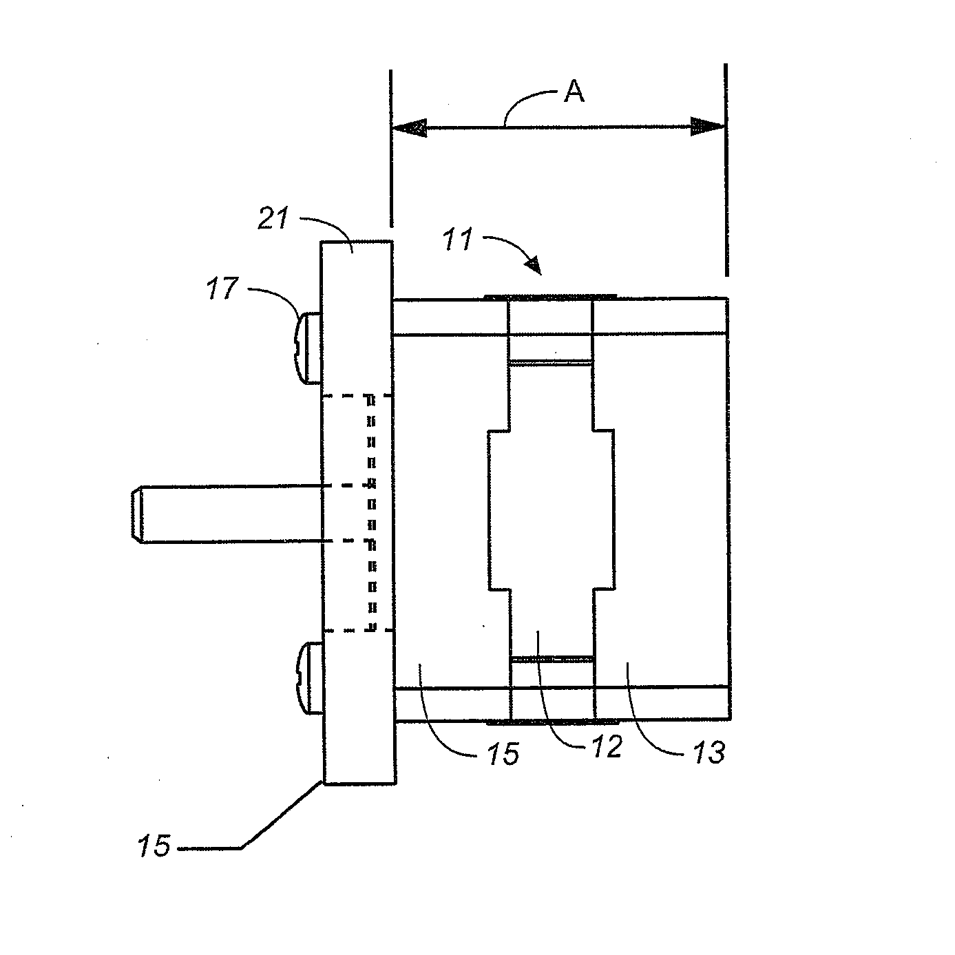
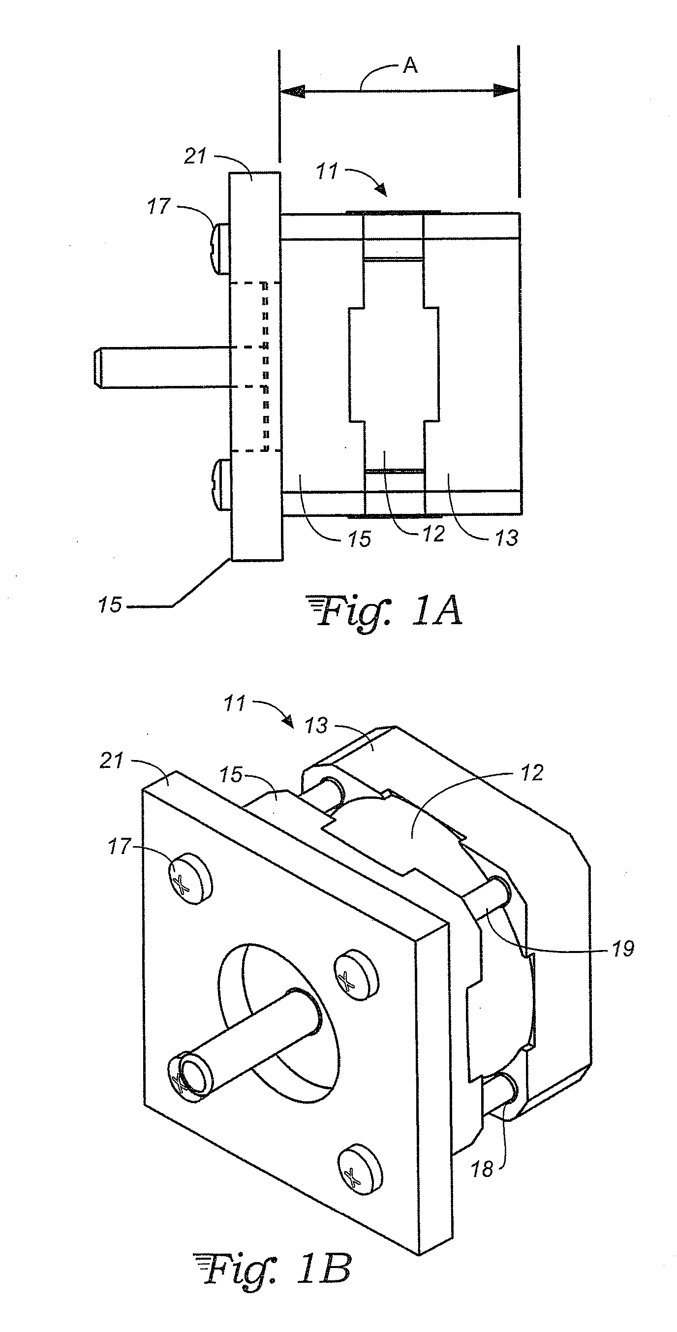
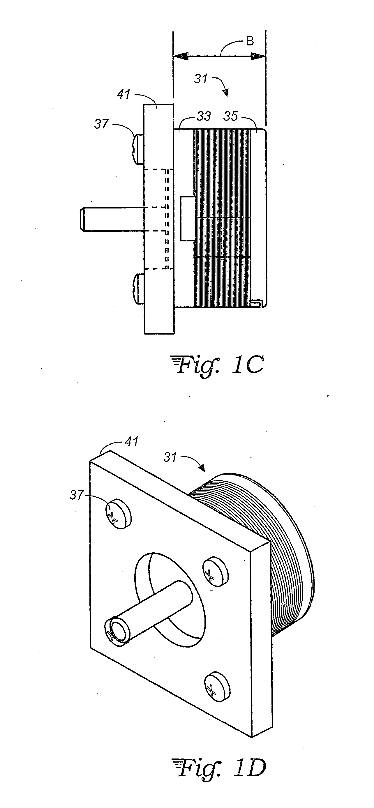
[0019]With reference to FIGS. 1A through 1D, prior art motor mounting structures are seen in both side and perspective views. In FIGS. 1A and 1B, a rear mounting configuration is shown, in which long screws 17 extend from the rear of the motor 11 into threads of a mounting plate 21 in order to secure the motor 11 to the plate 21. The rear end cap 13 extends outward beyond the perimeter of the stator 12 in order to accommodate apertures 18 for passage of the long screws 19. In particular, the stator 12 is circular in shape while the end caps' 13 and 15 are of square shape with the screw apertures 18 provided in the end cap corners. In FIGS. 1C and 1D, another motor 31 provides four mounting threads in the front end cap 33 for receiving short screws 37 extending from the face of the mounting plate 41 to which the motor 31 is mounted. The length of the screws 37 is limited by the thickness of the front end cap 33.

[0020]With reference to FIGS. 2A and 2B, and also 3A and 3B, examples of ...


PUM


Abstract

A step motor integrates its mounting face and heat sink into the stator design. In particular, mounting holes (typically, four in number) are provided through the stator stack in outer perimeter areas. The stator stack itself becomes the mounting surface, allowing the heat generated from the stator to conduct directly to the mounting plate. The front end cap for holding the rotor in alignment is situated inside of the stator's mounting surface and takes no part in mounting the motor to the mounting surface. The end caps only hold the rotor in proper relation within the stator and contain the bearing assembly for the rotor's axial drive shaft. The perimeter of the stator assembly between the mounting screw holes may have saw-tooth cutouts that define heat-dissipation fins.

Description

CROSS-REFERENCE TO RELATED APPLICATION[0001]This application claims priority under 35 U.S.C. 119(e) from U.S. provisional application No. 62 / 038,132, filed Aug. 15, 2014.TECHNICAL FIELD[0002]This invention relates generally to motor design for any field where a small motor size and fast heat dissipation are required, and relates more particularly to mounting structures provided for such motors.BACKGROUND ART[0003]The primary components of a motor include stator / winding assembly, rotor / shaft / bearing assembly, and two end caps. Some specific motor applications include their use in printers, security cameras, x-y tables, scanners, CNC machines, dispensers, injector pumps, turntables, optical equipment, and any precision devices of motion control system. Many of these applications either require or work better with a small motor size, including small dimensions measured from the mounting face to the rear of the motor.[0004]A traditional motor provides mounting threads (often four in num...

Claims


Application Information

Patent Timeline
Patent Type & Authority Applications(United States)
IPC IPC(8): H02K5/04H02K9/22H02K37/00
CPCH02K5/04H02K37/00H02K9/22H02K37/18H02K1/146H02K1/20H02K5/15H02K5/18
Inventor LIN, TED T.BADGEROW, RICHARD L.LIN, RYAN C.
Owner LIN ENG INC
Why Eureka
Try Eureka