Upset resistant mechanical seal

a mechanical seal and heat resistance technology, applied in the direction of engine seals, mechanical apparatus, engine components, etc., can solve the problems of excessive heat generation of mechanical seals, air gaps between parts, excessively high seal face temperatures, etc., to improve conduction, increase contact, and high thermal conductivity

Active Publication Date: 2011-09-06
FLOWSERVE MANAGEMENT CO
View PDF9 Cites 1 Cited by
  • Summary
  • Abstract
  • Description
  • Claims
  • Application Information

AI Technical Summary

Benefits of technology

[0011]The sheet material is used to enhance the conduction of heat from the seal face into the metal component, thereby reducing the seal face temperature and improving seal performance, especially in poor lubrication conditions such as dry running.
[0013]The graphite sheet material comprises a commercially available industrial grade flexible graphite flat sheet material, and has been shown to be effective in thicknesses from 0.005″ to 0.030″ in testing. Significant features of the sheet that enable conduction are: (1) the ability of the material to conform to the surface variations of both the seal face and metal part, increasing the contact between the parts and therefore the conductivity; (2) high thermal conductivity in the transverse plane of the sheet, which enables improved conduction in any areas where the sheet does not fully conform; and (3) high thermal conductivity in the axial plane of the sheet, which enables heat flow.
[0014]The general use of a gasket between a seal face and a metal component is provided in some seals. However, in these applications, the gasket material is not thermally conductive and only serves as a means to prevent damage or distortion to the seal faces.
[0016]The improved mechanical seal of the invention thereby enhances conduction of heat away from seal faces through the use of the flat graphite sheet wherein this feature can be incorporated into development of new mechanical seal products targeted toward chemical and general industrial applications worldwide. For this product alone, the performance increase caused by the sheet is significant in that it enhances the ability of the seal to survive and recover when encountering off design operation conditions that typically cause seal failure with existing seals. This improved heat transfer capability results in increased reliability and overall product life for the seals.

Problems solved by technology

Mechanical seals generate significant heat loads at an interface between a flat rotating seal face and an opposing flat stationary seal face.
In typical mechanical seals, the conduction coefficient is poor between a seal face and a metal part due to the rigid nature of both the mechanical seal face and the metal part, resulting in air gaps between the parts.
In dry running conditions, the continuing contact between the seal faces can lead to excessively high seal face temperatures wherein the excessive temperature can rapidly lead to seal failure such as by damaging the carbon seal rings and damaging O-rings, particularly those in contact with the other ring which may be made of silicon carbide.
This works well under normal operating conditions where convection is the primary mode of heat removal, however this does not solve the problem of high seal face temperatures associated with dry running conditions.
Lapping can improve the surface contact at the interface although this has the trade-off of significant additional expense.
In dry run tests conducted on a prototype mechanical seal design using a conventional direct metal conduction path from the mechanical seal face to a metal seal ring holder, the seal face temperature would reach excessive temperatures in under 10 minutes of dry running that were sufficiently elevated to damage the seals and cause seal failure.
This temperature would degrade the seal face materials and elastomers in contact with the seal faces, rapidly resulting in seal failure.
However, in these applications, the gasket material is not thermally conductive and only serves as a means to prevent damage or distortion to the seal faces.
In this instance, the gasket is a thermally conductive graphite material, but the carbon graphite seal face material is not thermally conductive and thus does not provide the operational benefit of heat removal from the interface defined between two opposed seal faces.
Hence, the carbon graphite seal impedes transfer of heat from the other seal ring.

Method used


Image

  • Upset resistant mechanical seal
  • Upset resistant mechanical seal
  • Upset resistant mechanical seal

Examples


Embodiment Construction

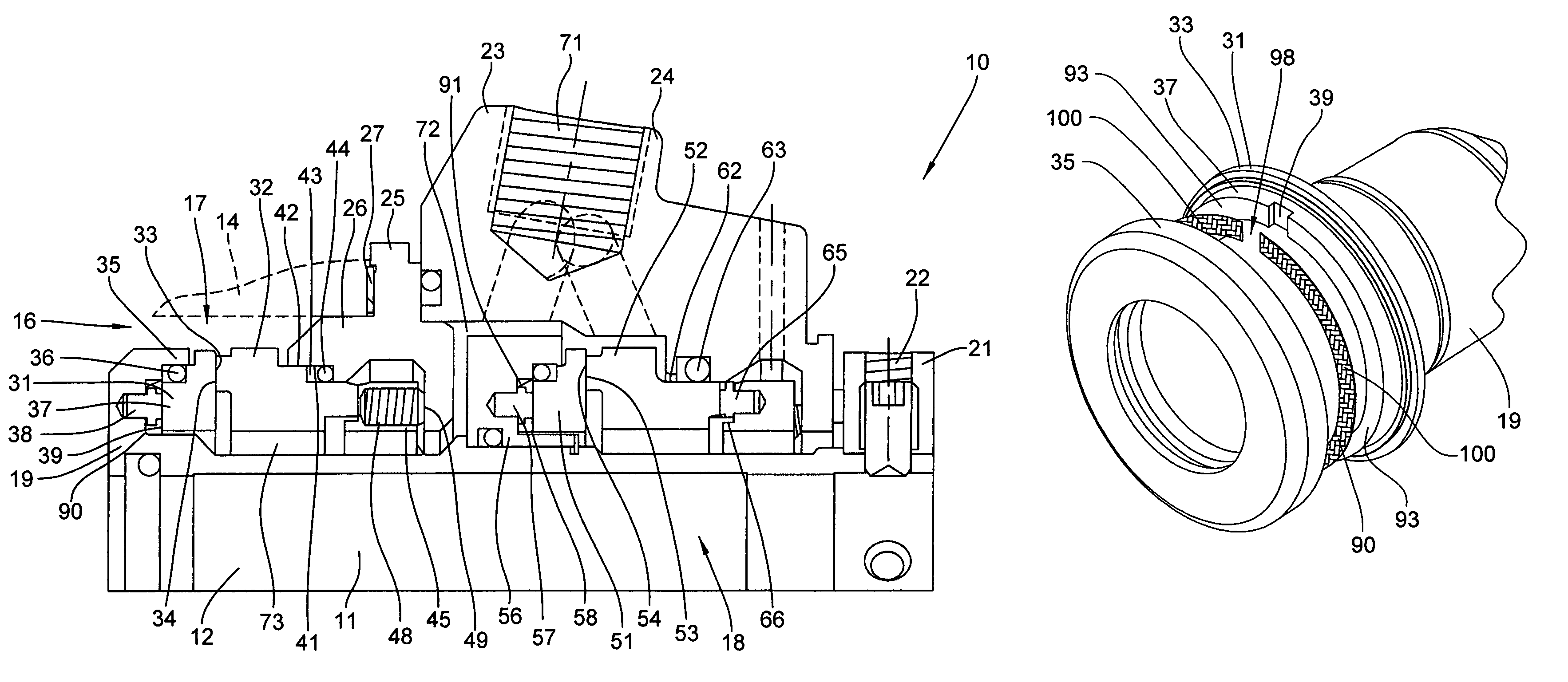
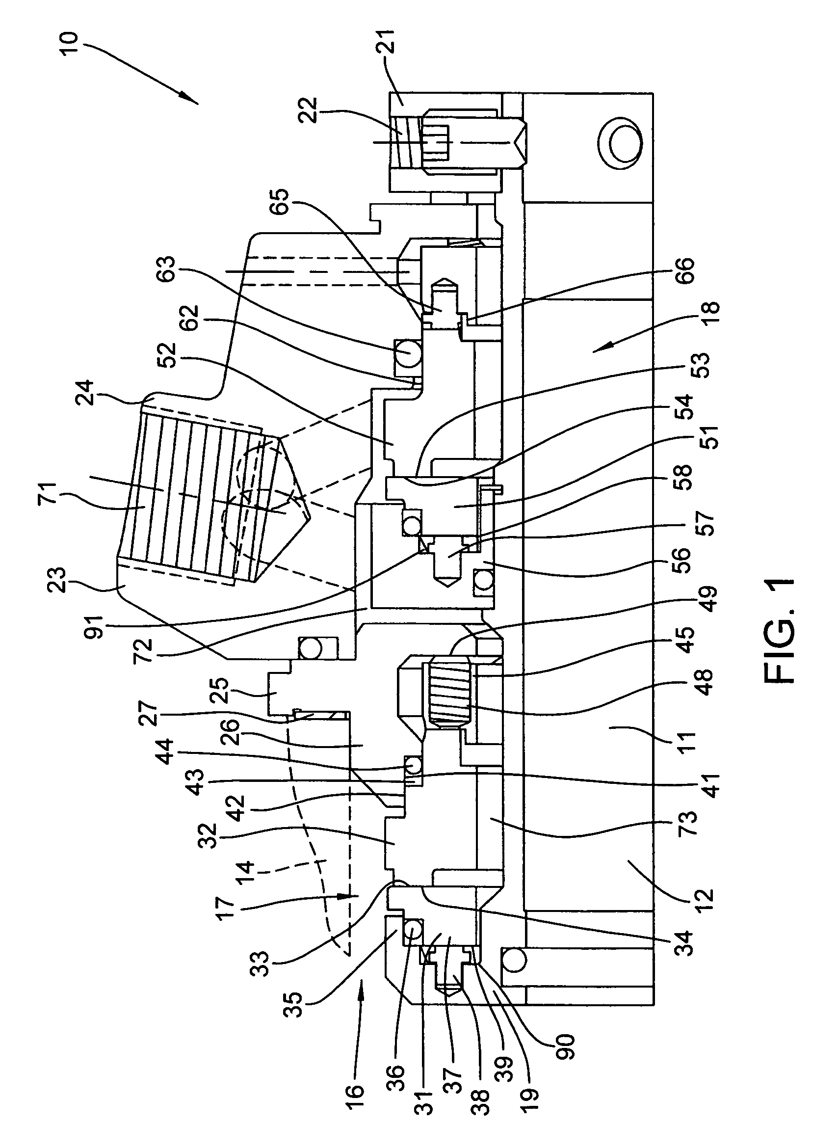
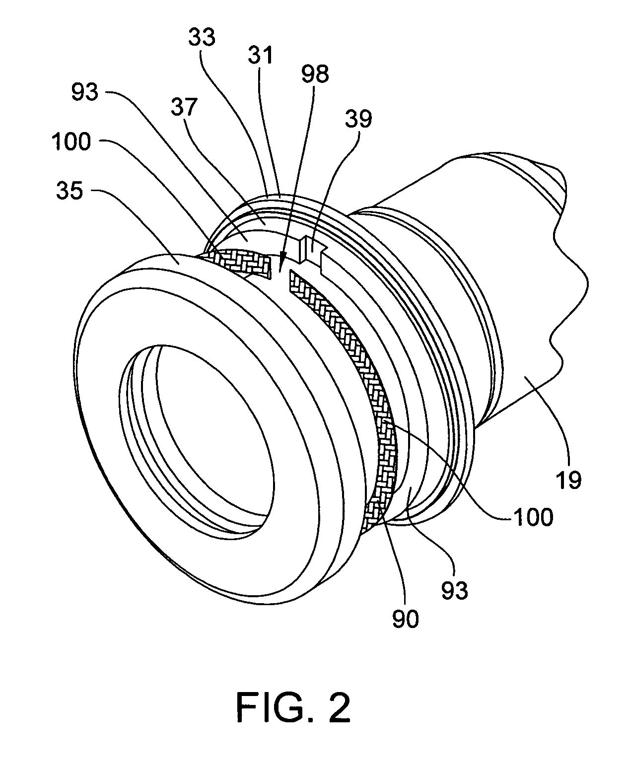
[0026]Referring to FIG. 1, a mechanical seal arrangement 10 according to the present invention is illustrated in a contacting, dual pusher seal configuration wherein the seal arrangement 10 is disposed in concentric relationship to an elongate shaft 11 which is rotatable about its axis 12 and driven by a motor (not illustrated) at one end and drives an equipment component such as an impeller at the opposite end. The double seal arrangement cooperates with a chamber or stuffing box 16 associated with a housing 14 of the equipment from which the shaft 11 protrudes, such as a pump targeted for use in chemical and general industrial applications.

[0027]The mechanical seal arrangement 10 includes an inner seal assembly 17 which is positioned more closely adjacent the product being handled, such as the pumping chamber, and an outer seal assembly 18 which is disposed outwardly of but axially in series with the inner seal assembly 17. These seal assemblies 17 and 18, in the illustrated embod...


PUM


Abstract

A mechanical seal face has a significant increase in the ability of the seal to tolerate poor lubrication conditions such as dry running. The mechanical seal employs a thin, non-corrugated flat sheet of flexible thermally conductive graphite material placed between one of the mechanical seal faces and a metal surface such as a metal surface defined by a shaft sleeve or gland serving as a seal ring holder. The graphite sheet is located axially between a back face of the more thermally conductive mechanical seal ring and the metal face holder part. The conductive seal face material preferably is a ceramic or cermet material such as silicon carbide, tungsten carbide, silicon nitride, aluminum oxide, or a metallic material such as stainless steel. Fluid pressure and spring forces are used to create a compressive load between the seal face, graphite sheet, and metal part to maximize continuous contact between the opposed faces of these parts and the opposite sides of the graphite sheet, and heat buildup at contacting seal faces flows away therefrom to the metal part through the thermally conductive sheet.

Description

CROSS-REFERENCE TO RELATED APPLICATION[0001]This application claims the benefit of U.S. Provisional Application Ser. No. 61 / 003,831, filed Nov. 20, 2007, which is incorporated herein by reference in its entirety.FIELD OF THE INVENTION[0002]The invention relates to a mechanical seal arrangement which is configured so as to dissipate excessive heat from mechanical seal faces resulting from upset conditions such as poor lubrication conditions which might occur during dry running of the mechanical seal.BACKGROUND OF THE INVENTION[0003]Mechanical seals generate significant heat loads at an interface between a flat rotating seal face and an opposing flat stationary seal face. These heat loads are due to contact friction between the faces and viscous shear of the lubricating fluid between the faces. Removal of this heat is typically through convection with the gas or liquid fluids at the surfaces of the rotating and stationary seal faces, and conduction at locations where the face comes in...

Claims


Application Information

Patent Timeline
Patent Type & Authority Patents(United States)
IPC IPC(8): F16J15/34
CPCF16J15/3404
Inventor FERRIS, JASON C.JACOBS, LARRY E.DESMIT, STEVEN D.GRIFFITH, DARYL L.SAAD, ANNE L.SEAMAN, JR., R. JAMES
Owner FLOWSERVE MANAGEMENT CO
Why Eureka
Try Eureka