
Thin Film of Solar Battery Structure, Thin Film of Solar Array and Manufacturing Method Thereof

Inactive Publication Date: 2012-02-16
SUNOVEL SUZHOU TECH
View PDF5 Cites 1 Cited by
  • Summary
  • Abstract
  • Description
  • Claims
  • Application Information

AI Technical Summary

Benefits of technology

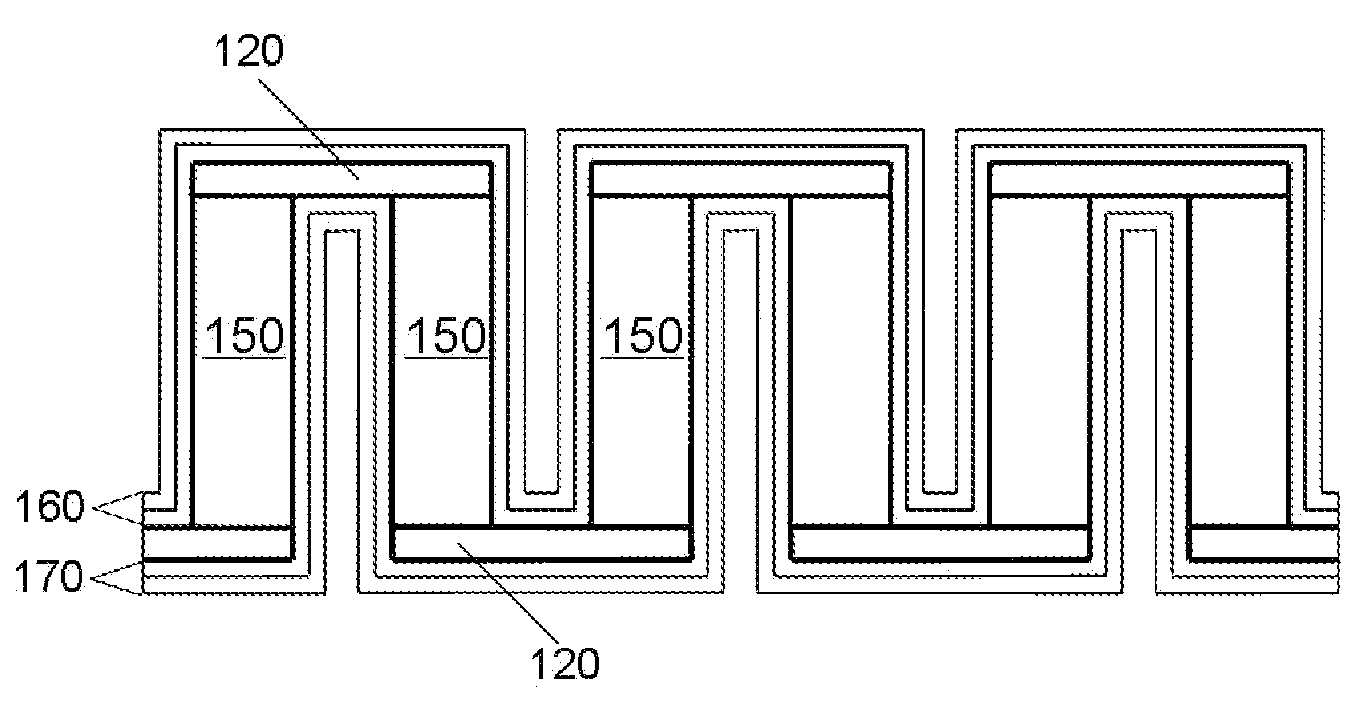
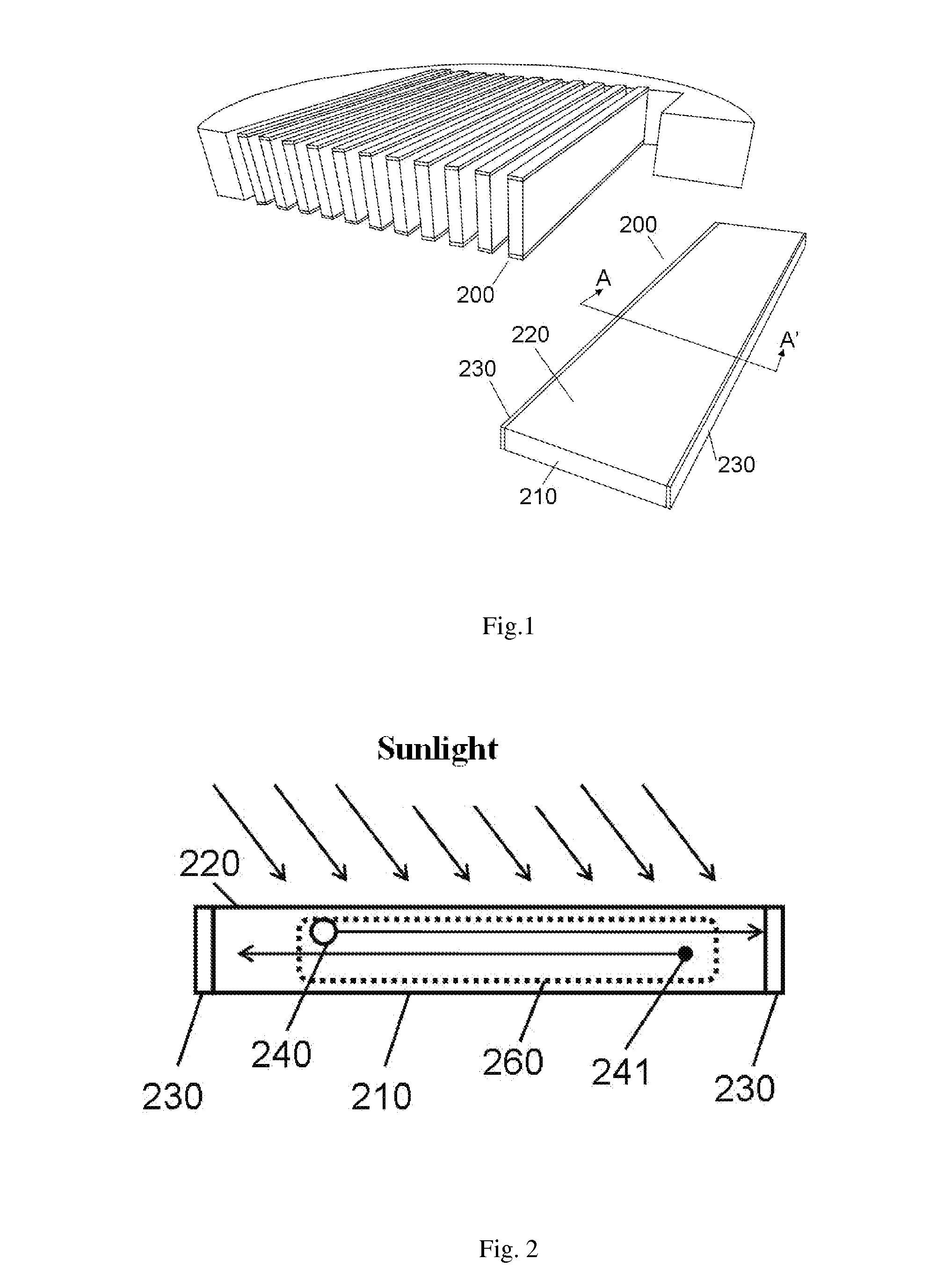
[0010]Through the manufacturing method according to embodiments of the present invention, the effective areas of the electrodes are increased by effectively utilizing the thickness of the substrate (or wafer), and the electrodes and the light entry surface are provided on the same side so as to effectively reduce the recombination distance, shorten the distance between the electrodes, reduce the recombination current of carriers and improve power generation efficiency. The cell structure of the present invention forms an insulation layer on each of the sidewalls of the semiconductor strip plate. On one hand, it reduces recombination of the carriers on the sidewall portion and further improves power generation efficiency; and on the other hand, a conductive layer coupled with the electrodes may be further formed on the insulation layer and the conductive layer may be isolated so as to prevent a possible short circuit between two electrodes, realize parallel connection between the structures in the cell array through the conductive layer, reduce connection resistance and improve power generation efficiency.

Problems solved by technology

Furthermore, the investment cost for the existing solar cell structure is relatively high, which hinders widespread applications of thin-film solar cells.

Method used


Image

  • Thin Film of Solar Battery Structure, Thin Film of Solar Array and Manufacturing Method Thereof
  • Thin Film of Solar Battery Structure, Thin Film of Solar Array and Manufacturing Method Thereof
  • Thin Film of Solar Battery Structure, Thin Film of Solar Array and Manufacturing Method Thereof

Examples


Embodiment Construction

[0018]Various embodiments of the present invention are described in more details below with reference to the accompanying drawings, wherein like reference numerals used throughout the description represent like components or components having like functions. The embodiments described in conjunction with the drawings below are merely illustrative and used to explain the present invention alone, and cannot be construed as limiting the present invention.

[0019]One aspect of the present invention relates to forming electrodes on planes in the thickness direction of a substrate and positioning electrodes and light entry surface of a solar cell on the same surface so as to reduce recombination distance, shorten distance between electrodes, reduce bulk recombination current and improve power generation efficiency. Furthermore, in the structures according to embodiments of the present invention, insulation layers are provided on both sides of a cell strip plate, which can further reduce the ...


PUM


Abstract

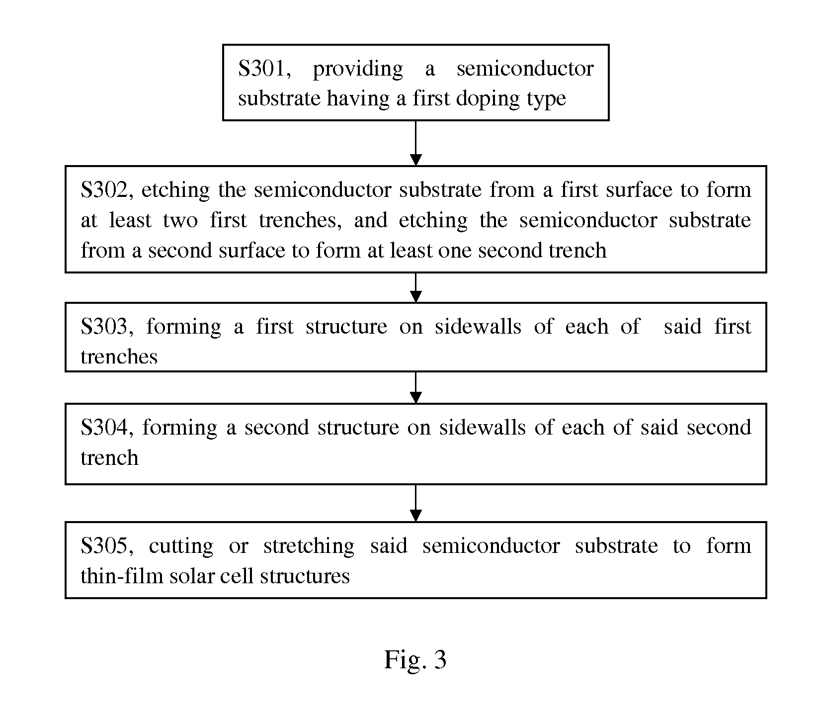
The present invention proposes a thin-film solar cell structure, a method for manufacturing the same and a thin-film solar cell array. The method for manufacturing thin-film solar cell structures comprises: forming at least two first trenches through a first surface into said semiconductor substrate, forming at least one second trench through a second surface into said semiconductor substrate, said second trench located between two neighboring said first trenches; forming a first structure on sidewalls of each of said first trenches; to forming a second structure on sidewalls of each of said second trench; and cutting or stretching said semiconductor substrate to form thin-film solar cell structures. The distance between the electrodes can be effectively shortened through the present invention such that the recombination rate between the electrons and the holes can be reduced and the bulk recombination current and the surface recombination current can be reduced to achieve the objective of improving power generation efficiency. The thin-film solar cell structure and the method for manufacturing the same proposed in the present invention can also save semiconductor material and reduce production cost.

Description

FIELD OF THE INVENTION[0001]The present invention relates to the field of solar cell manufacturing, and more specifically, to a new, highly efficient and low-cost thin-film solar cell structure, array and a method for manufacturing the same.BACKGROUND OF THE INVENTION[0002]A thin-film solar cell, just as its name implies, is a solar cell prepared from a thin film, which uses a very small amount of semiconductor material and thus makes it easy to reduce the cost thereof. Meanwhile, it is not only a highly efficient source of energy, but can also be used as a novel building coating material, which makes it easy to realize a perfect combination with architecture. As raw silicon materials continue to be in short supply on the global market, thin-film solar cells have become a new trend and a new focus in development of the global photovoltaic market. At present, there are three types of thin-film cells that have entered the phase of industrialized mass production, i.e. silicon-based thi...

Claims


Application Information

Patent Timeline
IPC IPC(8): H01L31/0376H01L27/142H01L31/18
CPCY02E10/50H01L31/035281H01L31/0392
Inventor ZHU, HUILONGLUO, ZHIJIONGYIN, HAIZHOU
Owner SUNOVEL SUZHOU TECH
Learn More