Active switching rectifier employing mosfet and current-based control using a hall-effect switch

a technology of hall-effect switch and active switching rectifier, which is applied in the direction of voltage/current isolation, magnetic field measurement using galvano-magnetic devices, instruments, etc., can solve the problems of reducing the reliability and efficiency of equipment, power loss can be significant, and the control circuit of mosfet is complex

Active Publication Date: 2016-02-18
ZHANG YIQIANG JAKE
View PDF3 Cites 17 Cited by
  • Summary
  • Abstract
  • Description
  • Claims
  • Application Information

AI Technical Summary

Benefits of technology

[0007]An object of the present invention is to provide a rectifier circuit for high current application that is efficient and has a simple structure.

Problems solved by technology

Thus, in high current rectifier applications, such as those encountered in alternators in automobiles and other applications, power loss can be significant.
In high current rectifier applications, such as 150 A or higher in a 125° C. environment, the heat generated from diode power loss can greatly reduce the reliability and efficiency of the equipment.
This type of MOSFET control circuits tend to be complex, and have the disadvantage that voltage detection may become unreliable in applications that involve dynamic inductive or capacitive load.

Method used


Image

  • Active switching rectifier employing mosfet and current-based control using a hall-effect switch
  • Active switching rectifier employing mosfet and current-based control using a hall-effect switch
  • Active switching rectifier employing mosfet and current-based control using a hall-effect switch

Examples


first embodiment

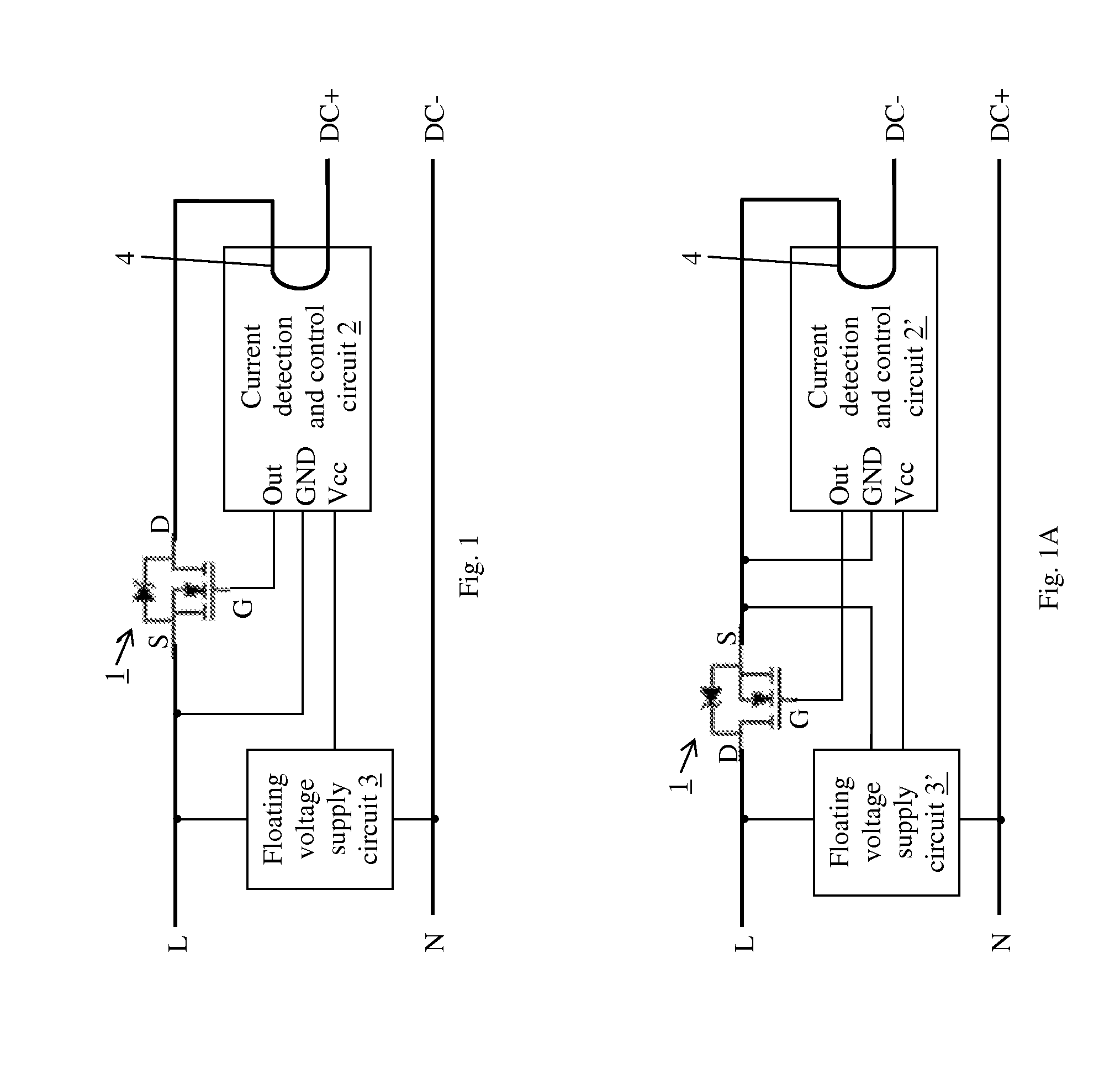
[0031]FIG. 1 is a schematic diagram showing an active switching rectifier circuit according to the present invention, in a single phase half wave configuration. The active switching rectifier circuit includes a MOSFET 1, which is preferably an N-channel power MOSFET, a current detection and control circuit 2, and a voltage supply circuit 3. The AC input for this circuit is a single phase AC source having a phase line L and neutral line N. The source electrode S of the MOSFET 1 is coupled to the input phase line L and its drain electrode D is coupled to the positive DC output DC+. The AC neutral line N acts as the negative DC output DC−. The DC load is connected between DC+ and DC−. The current that passes through the MOSFET 1 flows through an input conductor 202 of the current detection and control circuit 2. The current detection and control circuit 2 does not have any electrical element on the current path except for the conductor 202 itself, which has a negligible resistance. The...

second embodiment

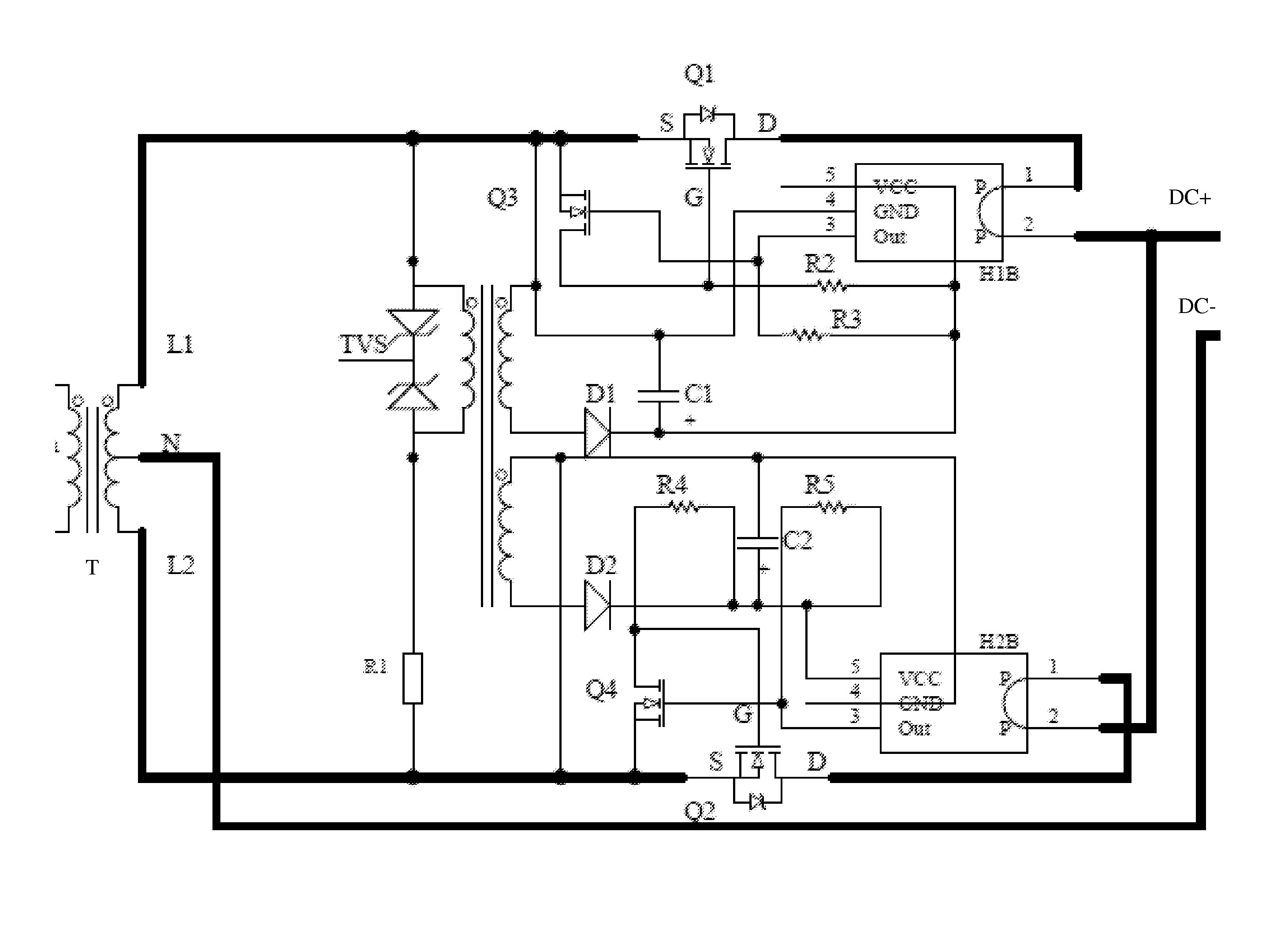
[0065]FIG. 5 is a schematic diagram showing an active switching rectifier circuit according to the present invention, in a center-tap, two-phases, full-wave configuration. This circuit has first and second power MOSFETs Q1 and Q2 respectively connected on the first and second phase lines L1 and L2 of the AC power source, corresponding first current detection and control circuit (H1B, Q3, R2, R3) and second current detection and control circuit (H2B, Q4, R4, R5) for controlling the first and second MOSFETs, and a floating voltage pump which separately supplies voltages to the first and second current detection and control circuits. The current detection and control circuits are similar to the current detection and control circuit 20A of FIG. 4 (e.g. components H1B and H2B are similar to H1B in FIG. 4) but have their grounds respectively connected to the first and second phase lines L1 and L2.

[0066]The floating voltage pump in FIG. 5 includes a center tap dual output transformer T, tr...

third embodiment

[0068]FIG. 6 is a schematic diagram showing an active switching rectifier circuit according to the present invention, in a single-phase, full-bridge configuration. This circuit has first through fourth power MOSFETs Q1 to Q4, first current detection and control circuit (H1B, Q5, R1, R2) and second current detection and control circuit (H2B, Q6, R3, R4) for controlling the four MOSFETs, and a floating voltage pump (dual output transformer T, D1, C1, D2 and C2) which separately supplies the first and second current detection and control circuits.

[0069]The four MOSFETs form a full bridge: Q1 and Q4 conduct during the positive half wave of the AC source to output the voltage at the positive DC output DC+; Q2 and Q4 conduct during the negative half wave of the AC source to output the voltage at DC+.

[0070]Each current detection and control circuit is similar to the current detection and control circuit 20A of FIG. 4 (e.g. components H1B and H2B are similar to H1B in FIG. 4) but have their...


PUM


Abstract

An active switching rectifier circuit uses a MOSFET and applies a current based control to turn the MOSFET on and off. The MOSFET has its source and drain connected between an AC phase or neutral line and the DC output. A current detection and control circuit has an input current conductor coupled in series with the source-drain current of the MOSFET; it outputs a switching control signal based on the current in its input conductor and applies the signal to the gate of the MOSFET for on / off control. A Hall-effect switch may be used in the current detection and control circuit. The rectifier may also include a voltage supply circuit for supplying a DC voltage to the current detection and control circuit. The rectifier circuit can be adapted for various configurations including single-phase half-wave, center-tap dual-phase full-wave, single-phase full-wave, and three-phase full-wave.

Description

BACKGROUND OF THE INVENTION[0001]1. Field of the Invention[0002]This invention relates to a rectifier circuit, and in particular, it relates to an active switching rectifier circuit employing MOSFETs with current-based control.[0003]2. Description of the Related Art[0004]Conventional AC to DC rectifying circuits employ diodes by utilizing the diode's P-N junction single direction conductivity. When a relatively small current passes through the diode, the normal diode will have a 0.7V voltage drop across the diode (or about 0.3V for Schottky type diodes). The voltage drop can be up to 1.0V or higher when a relatively high current, such as 100 A or 200 A, passes through the diode. The power loss over the diode will be 100 W or 200 W or more in such situations. Thus, in high current rectifier applications, such as those encountered in alternators in automobiles and other applications, power loss can be significant. In high current rectifier applications, such as 150 A or higher in a 12...

Claims


Application Information

Patent Timeline
Patent Type & Authority Applications(United States)
IPC IPC(8): H02M1/00H02M7/217
CPCH02M1/00H02M2001/0009H02M7/217H02M1/0009H02M7/2195H02M7/219G01R33/077G01R33/07G01R33/075G01R21/08G01R15/202G01R15/20G01R33/06Y02B70/10
Inventor ZHANG, YIQIANG, JAKE
Owner ZHANG YIQIANG JAKE
Why Eureka
Try Eureka