Hybrid induction welding process applied to piston manufacturing

a hybrid welding and piston technology, applied in the field of pistons, can solve the problems of residual stress and/or cracking along the weld, and friction welding is known to create a significant amount of flash or scrap material in the cooling chamber of the piston

Active Publication Date: 2016-03-03
TENNECO
View PDF4 Cites 3 Cited by
  • Summary
  • Abstract
  • Description
  • Claims
  • Application Information

AI Technical Summary

Benefits of technology

The hybrid induction welding process described in this patent has one advantage that is really important - it allows for accurate positioning of the piston parts when they are joined together. The piston parts start the process in a specific position, and at the end of the process, they are in that same position. This is important because it ensures that the piston parts are joined together correctly, and there are no mistakes in the alignment. The accuracy of the positioning is important because it helps to create a high-quality piston assembly that works properly.

Problems solved by technology

However, friction welding is known to create a significant amount of flash or scrap material in the cooling chamber of the piston, as well as residual stress and / or cracking along the weld.
However, these joining methods are known to cause residual stress, inadequate strength, and / or cracking along the weld.

Method used


Image

  • Hybrid induction welding process applied to piston manufacturing
  • Hybrid induction welding process applied to piston manufacturing
  • Hybrid induction welding process applied to piston manufacturing

Examples


Embodiment Construction

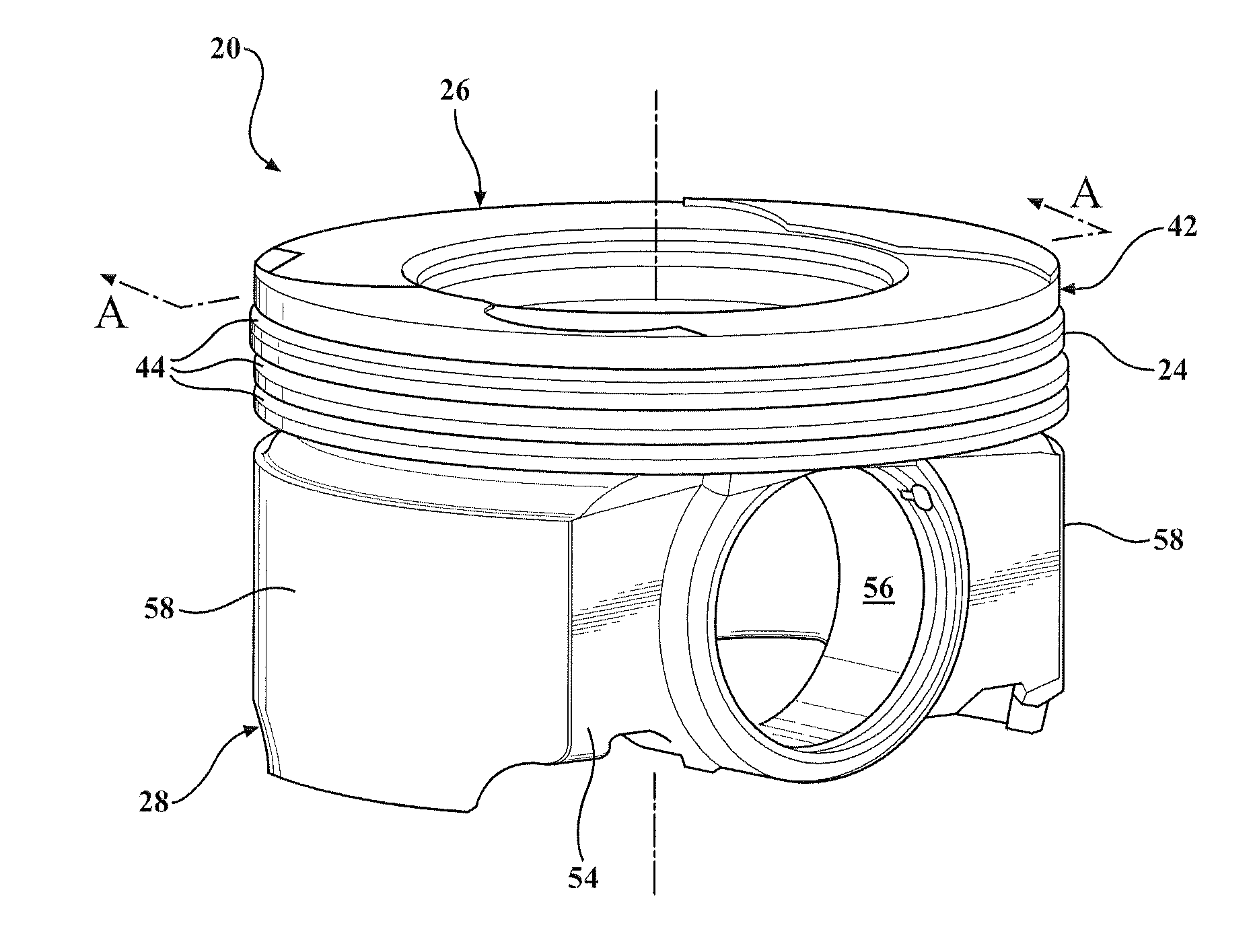
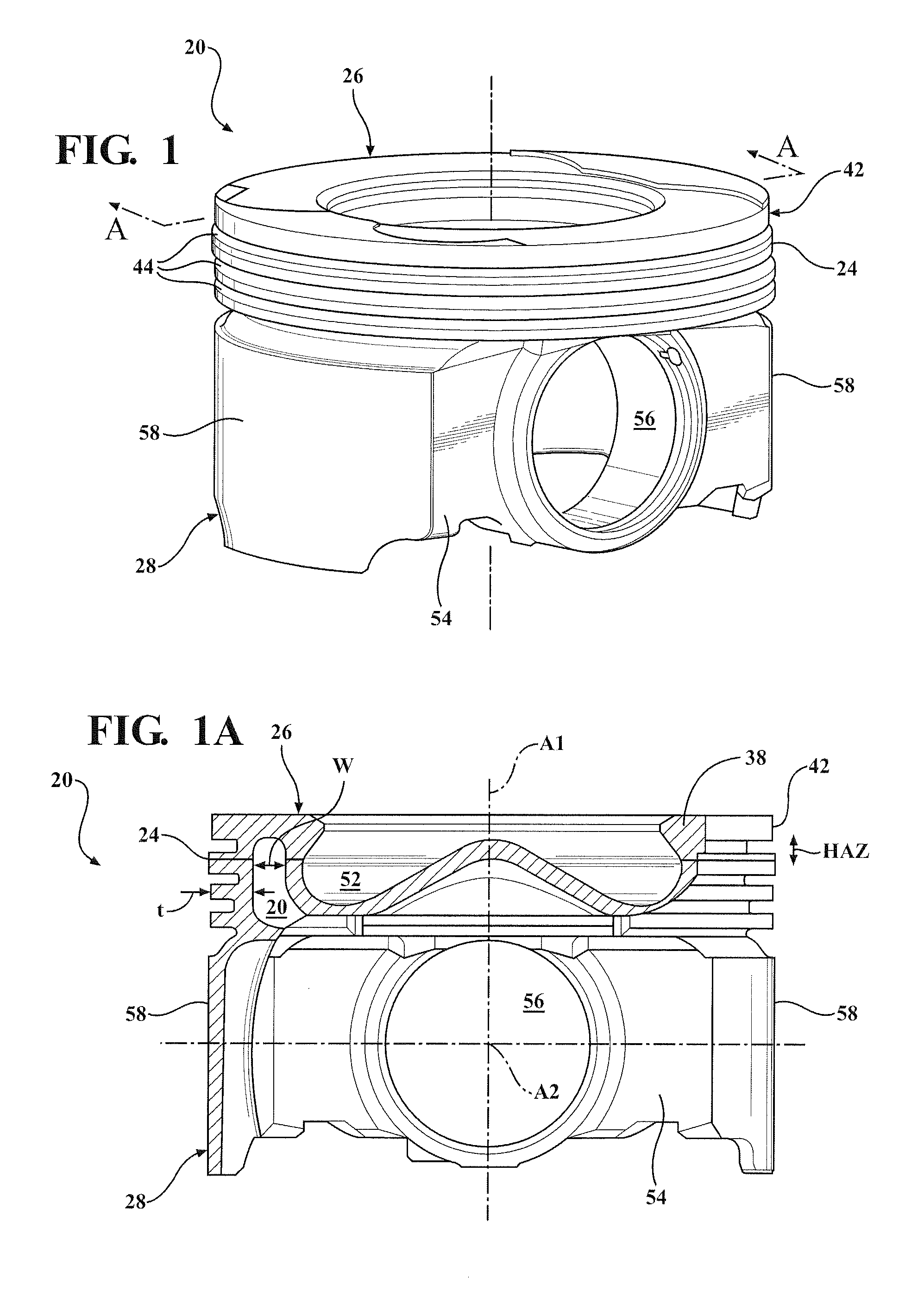
[0016]One aspect of the invention provides a method of manufacturing a piston 20 for an internal combustion engine, such as a small diameter steel piston 20 with a narrow cooling chamber 22, as shown in FIGS. 1 and 1A, for use in a light vehicle diesel (LVD) system. The method is referred to as a hybrid induction welding method and includes a unique combination of position and force control. The method produces a strong weld 24 between an upper piston part 26 and a lower piston part 28, as well as a homogenous metallurgical bond across the weld 24.

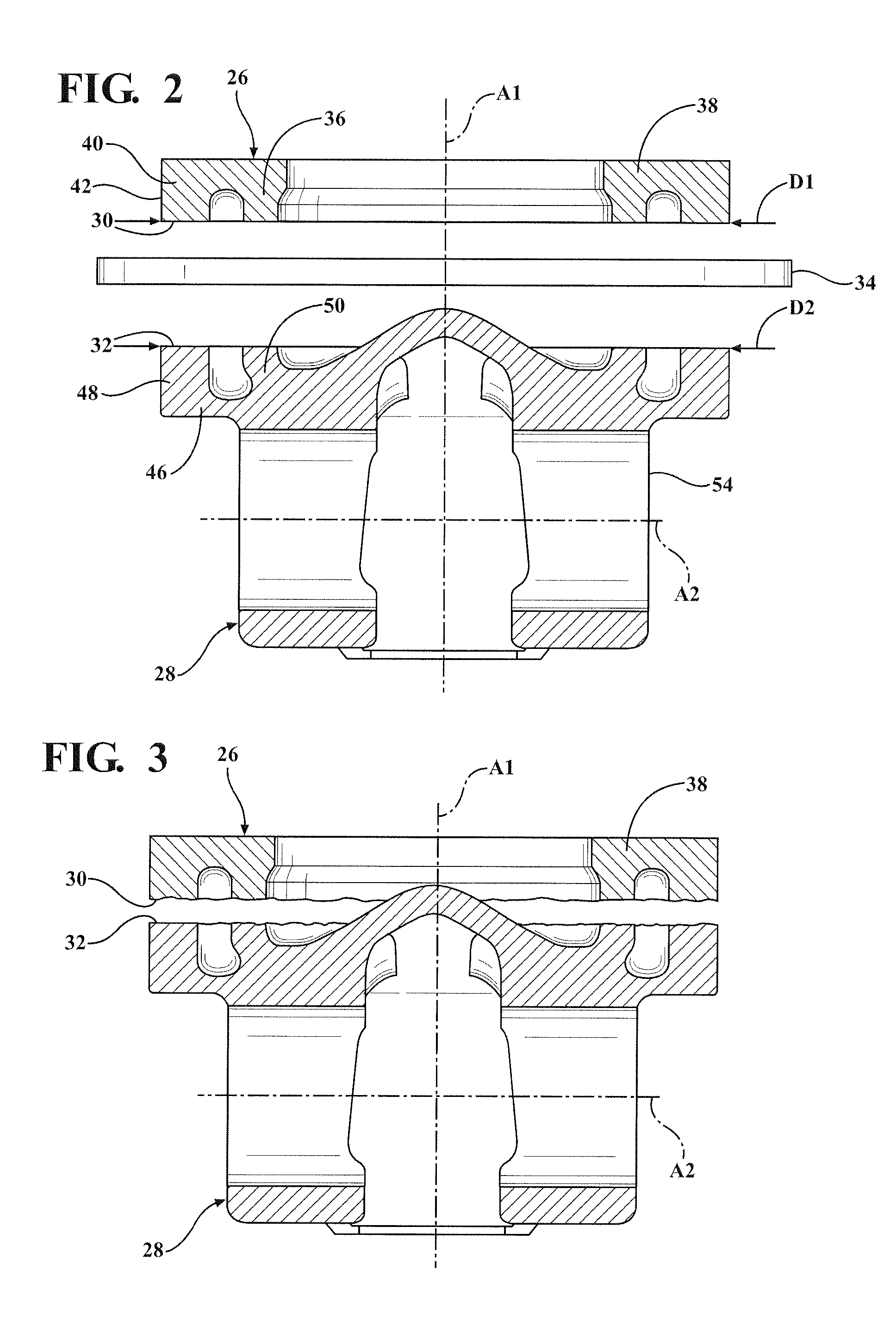
[0017]The method begins by providing the upper piston part 26 and the lower piston part 28 which are used to form the piston 20. The piston parts 26, 28 are typically formed of steel, but can be formed of another type of metal or metal alloy. An upper joining surface 30 of the upper piston part 26 is axially aligned with and spaced from a lower joining surface 32 of the lower piston part 28, as shown in FIG. 2. The method then includes hea...


PUM

PropertyMeasurementUnit
pressureaaaaaaaaaa
lengthaaaaaaaaaa
temperatureaaaaaaaaaa

Abstract

A hybrid induction welded piston including an upper piston part welded to a lower piston part is provided. The piston is produced by induction heating the upper piston part and the lower piston part, and bringing the parts together to a part growth compensated position. The method then includes rotating the upper piston part 17 to 34 degrees clockwise and then 17 to 34 degrees counterclockwise. In addition to controlling the axial position and degree of rotation, the force applied to the piston parts is controlled so that preferably no flash is formed in a narrow cooling chamber of the piston. During the rotating steps, the pressure gradually increases to a maximum level which occurs while the upper piston part is rotating in the second direction. The piston includes a homogenous metallurgical bond across the weld and no indentation on the outer surface at the weld prior to machining.

Description

BACKGROUND OF THE INVENTION[0001]1. Field of the Invention[0002]This invention relates generally to pistons, including light vehicle diesel pistons for internal combustion engines, and methods for manufacturing the same.[0003]2. Related Art[0004]Pistons used in internal combustion engines typically include an upper piston part joined to a lower piston part. Various methods are known for joining the piston parts together. One common joining technique is friction welding, which includes continuously rotating at least one of the piston parts about its center axis at a high speed and under pressure against the other piston part. However, friction welding is known to create a significant amount of flash or scrap material in the cooling chamber of the piston, as well as residual stress and / or cracking along the weld. Resistance welding and laser welding have also been used to join piston parts together. However, these joining methods are known to cause residual stress, inadequate strength...

Claims


Application Information

Patent Timeline
Patent Type & Authority Applications(United States)
IPC IPC(8): F02F3/00B21J5/08B21K3/00B23K13/01B23K31/12
CPCF02F3/003B23K13/015F02F2003/0061B21K3/00B21J5/08B23K31/12B23P15/10B23K20/129B23K20/24B23K28/02B23K2201/003B23K2101/003
Inventor ROELOFS, ZACHARY, ODELMARTINS, AIRTONEVERS, ROSSGARZA, OSCAR
Owner TENNECO
Why Eureka
Try Eureka