Lcl capacitor current compensation and control method based on division and summation technique

Inactive Publication Date: 2016-03-03
NATIONAL TSING HUA UNIVERSITY
View PDF0 Cites 13 Cited by
  • Summary
  • Abstract
  • Description
  • Claims
  • Application Information

AI Technical Summary

Benefits of technology

[0008]In view of the problems and drawbacks of the prior art, the present invention provides an LCL capacitor current compensation an

Problems solved by technology
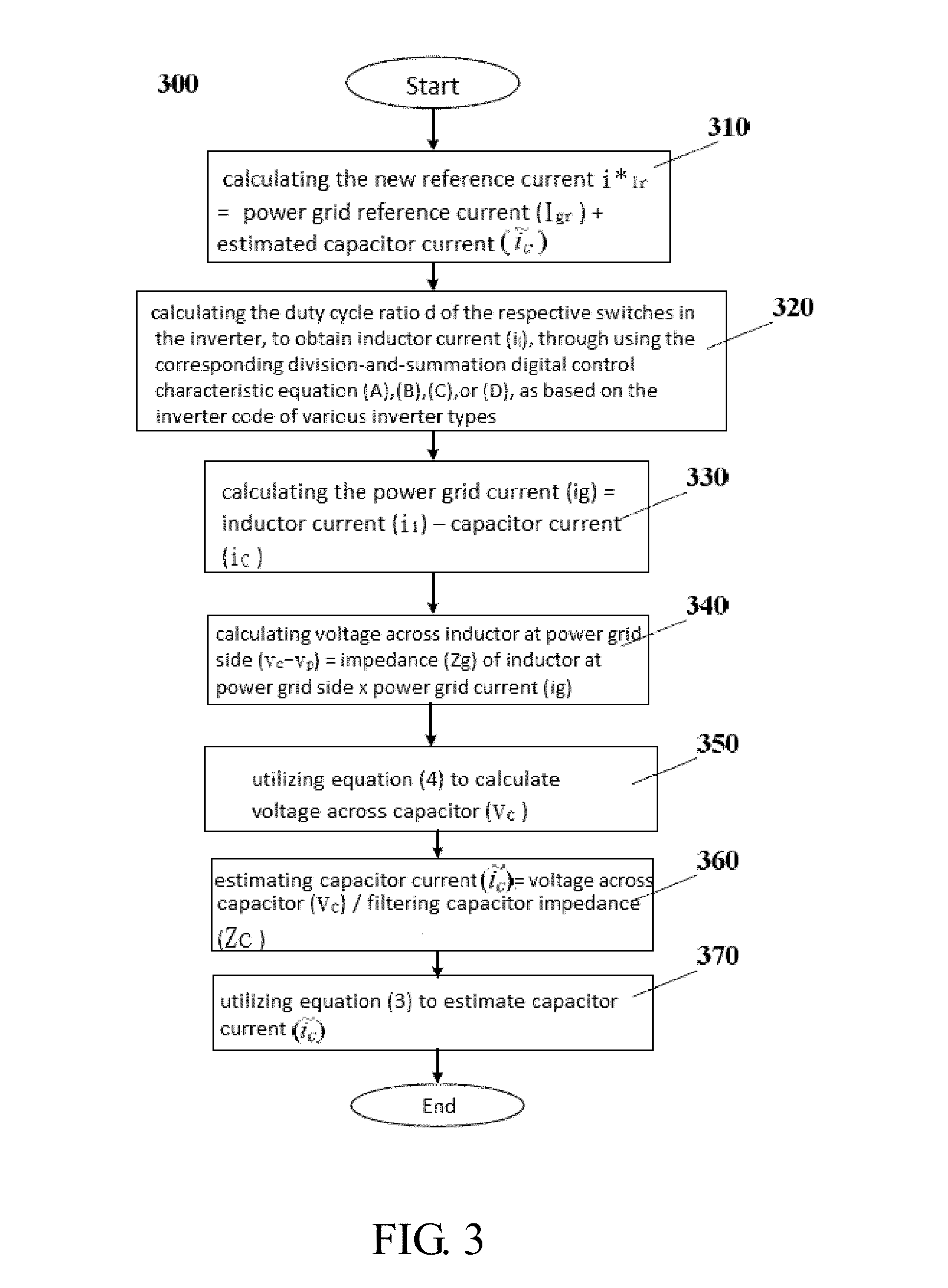
Any deviation from this value is co

Method used


Image

  • Lcl capacitor current compensation and control method based on division and summation technique
  • Lcl capacitor current compensation and control method based on division and summation technique
  • Lcl capacitor current compensation and control method based on division and summation technique

Examples


first embodiment

Single-Phase Double-Wire Bi-Directional Inverter System

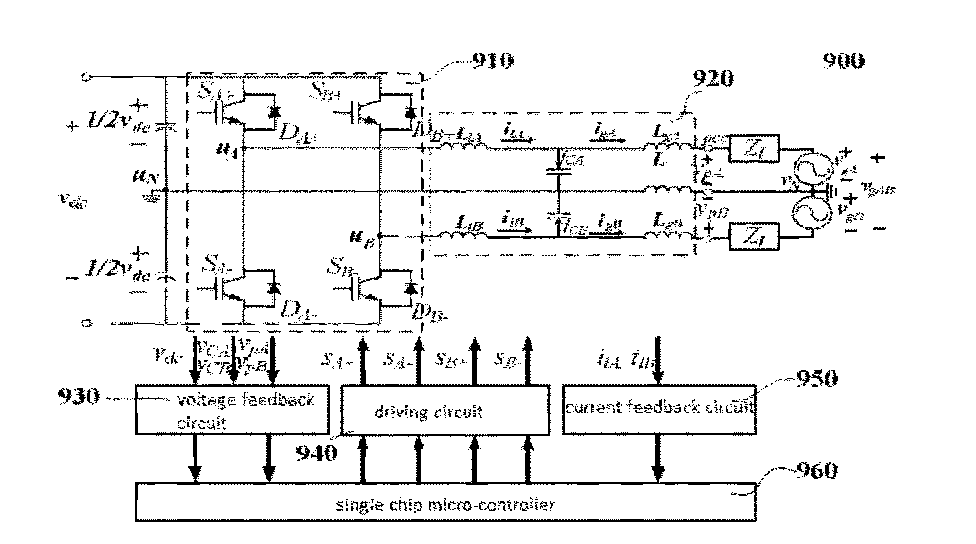
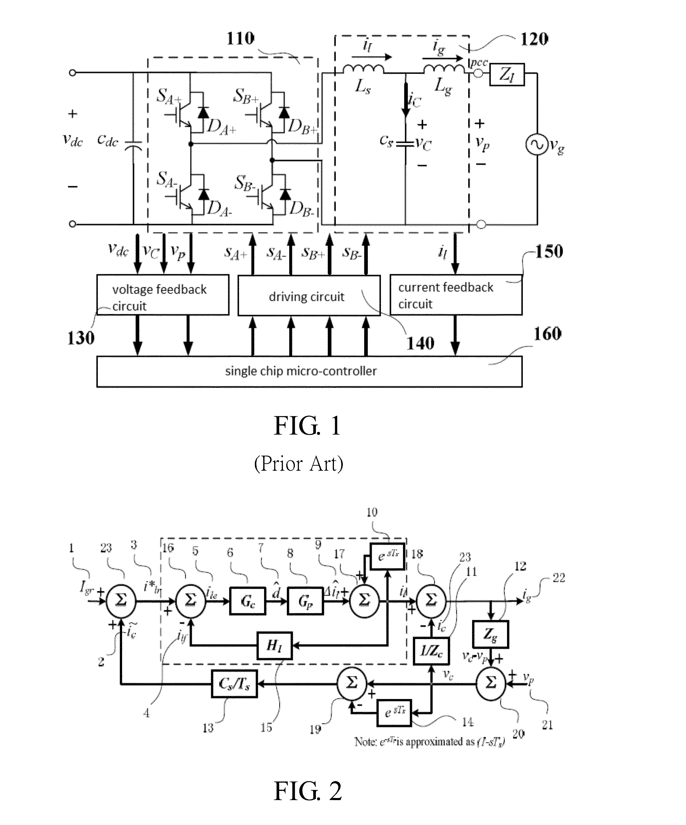
[0031]Firstly, refer to FIG. 1 for a circuit and control block diagram for a single-phase double-wire bi-directional inverter system according to a first embodiment of the present invention. The single-phase double-wire bi-directional inverter system itself belongs to the prior art. However, in the present embodiment, the inverter system is used together with the method and equations of the present invention, to modify inverter reference current to compensate for the distorted capacitor current caused by distorted voltage, in achieving suppressing merged grid current harmonics and generating ideal current of sine waves.

[0032]As shown in FIG. 1, the single-phase double-wire bi-directional inverter system 100 includes: a single-phase double-wire bi-directional inverter 110; an LCL filter 120, a voltage feedback circuit 130, a driving circuit 140, a current feedback circuit 150, and a single chip micro-controller 160. Wherein, the ...

second embodiment

Three-Phase Four-Wire Bi-Directional Inverter System

[0047]Refer to FIG. 7 for a circuit and control block diagram for a three-phase four-wire bi-directional inverter system according to a second embodiment of the present invention. The three-phase four-wire bi-directional inverter system itself belongs to the prior art. However, in the present embodiment, the inverter system is used together with the method and equations of the present invention, to modify inverter reference current to compensate for the distorted capacitor current caused by distorted voltage, in achieving suppressing merged grid current harmonics and generating ideal current of sine waves.

[0048]As shown in FIG. 7, the three-phase four-wire bi-directional inverter system 700 includes: a three-phase four-wire bi-directional inverter 710; an LCL filter 720, a direct current chain voltage feedback circuit 730, a driving circuit 740, a current feedback circuit 750, a voltage feedback circuit 760, and a single chip micro...

third embodiment

Three-Phase Three-Wire Bi-Directional Inverter System

[0054]Refer to FIG. 8 for a circuit and control block diagram for a three-phase three-wire bi-directional inverter system according to a third embodiment of the present invention. The three-phase three-wire bi-directional inverter system itself belongs to the prior art. However, in the present embodiment, the inverter system is used together with the method and equations of the present invention, to modify inverter reference current to compensate for the distorted capacitor current caused by distorted voltage, in achieving suppressing merged grid current harmonics and generating ideal current of sine waves.

[0055]As shown in FIG. 8, the three-phase three-wire bi-directional inverter system 800 includes: a three-phase three-wire bi-directional inverter 810; an LCL filter 820, a direct current chain voltage feedback circuit 830, a driving circuit 840, a current feedback circuit 850, a voltage feedback circuit 860, and a single chip ...


PUM


Abstract

An LCL capacitor current compensation and control method based on division and summation technique, comprising following steps: calculating new reference current i*lr=power grid reference current (Igr)+estimated capacitor current (); calculating duty cycle ratio d of respective switches in inverter to obtain inductor current (il), through using corresponding division-and-summation digital control characteristic equation (A), (B), (C), or (D), as based on inverter code of various inverter types; calculating power grid current (ig)=inductor current (il)−capacitor current (ic); calculating voltage across inductor at power grid side (vc−vp)=impedance (Zg) of said inductor at power grid side x power grid current (ig); utilizing equation (4) to calculate voltage across capacitor (vc); estimating capacitor current ()=voltage across said capacitor (vc)/filtering capacitor impedance (Zc); and utilizing equation (3) to estimate capacitor current ().

Description

BACKGROUND OF THE INVENTIONField of the Invention[0001]The present invention relates to an LCL capacitor current compensation and control method, and in particular to an LCL capacitor current compensation and control method based on division and summation technique.THE PRIOR ARTS[0002]With the advent of the Industrial Revolution since the 18th century, the petrochemical fuel, such as coal, petroleum, and natural gas are utilized and consumed in huge quantities. However, due to the exploitation for more than two hundred years, the energy resources are near depletion, and the energy crisis is getting serious. According to a survey conducted recently, with the petroleum resources presently available, it can only sustain industrial development and consumption for several decades before it comes to a complete depletion. In addition, for the uranium used for nuclear power generation, that will also be used up in the coming decades. Therefore, the green energy power generation is considere...

Claims


Application Information

Patent Timeline
IPC IPC(8): G01R31/40H02M1/12
CPCG01R31/40H02M1/12H02M1/126H02M7/53873H02M7/797H02M1/0009
Inventor WU, TSAI-FULIN, LI-CHUNYAO, NING
Owner NATIONAL TSING HUA UNIVERSITY
Why Eureka
Try Eureka