Refrigeration cycle device

a cycle device and refrigerant technology, applied in the field of refrigeration cycle devices, can solve the problem that the ventilation air cannot be sufficiently heated by the interior condenser, and achieve the effect of suppressing an increase in pressure loss, improving the cycle coefficient of performance, and preventing the dryness of the refrigerant flowing out of the exterior heat exchanger

Active Publication Date: 2016-03-10
DENSO CORP
View PDF8 Cites 20 Cited by
  • Summary
  • Abstract
  • Description
  • Claims
  • Application Information

AI Technical Summary

Benefits of technology

[0010]Refrigeration cycle devices for use in general vehicle air conditioners are designed to control the refrigerant evaporation temperature at the interior evaporator to be at least 0° C. or more in order to prevent frost formation (frost) on the interior evaporator.
[0020]Therefore, the increase in refrigerant evaporation temperature at the exterior heat exchanger can be suppressed to thereby increase the amount of heat absorbed by the refrigerant from the outside air in the exterior heat exchanger. As a result, the refrigeration cycle device can improve the heating capacity of the refrigerant radiator for the ventilation air when performing the dehumidification heating of the space to be air-conditioned.

Problems solved by technology

As a result, in the dehumidification heating mode at the low outside air temperature, the ventilation air cannot be sufficiently heated by the interior condenser.

Method used


Image

  • Refrigeration cycle device
  • Refrigeration cycle device
  • Refrigeration cycle device

Examples


first embodiment

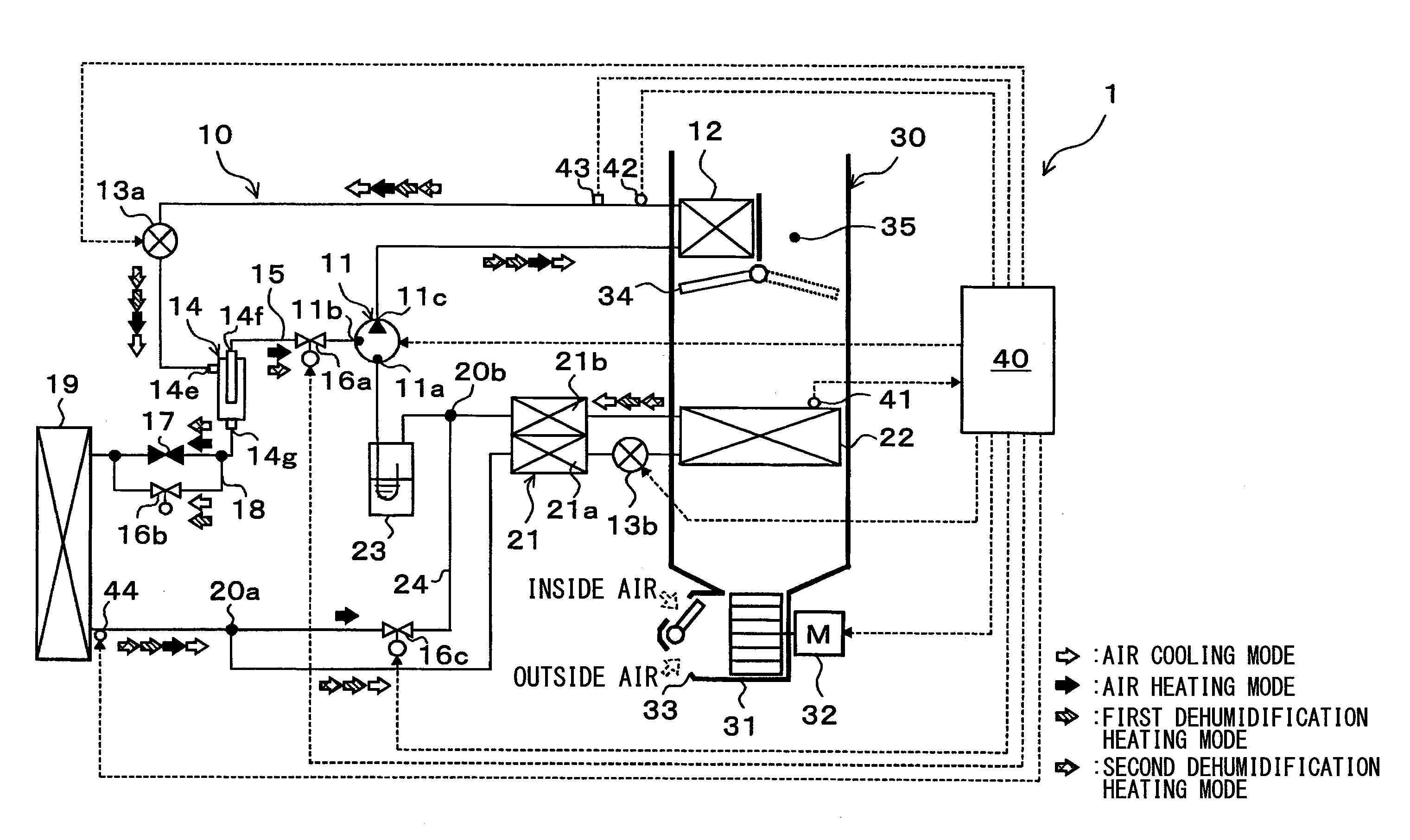
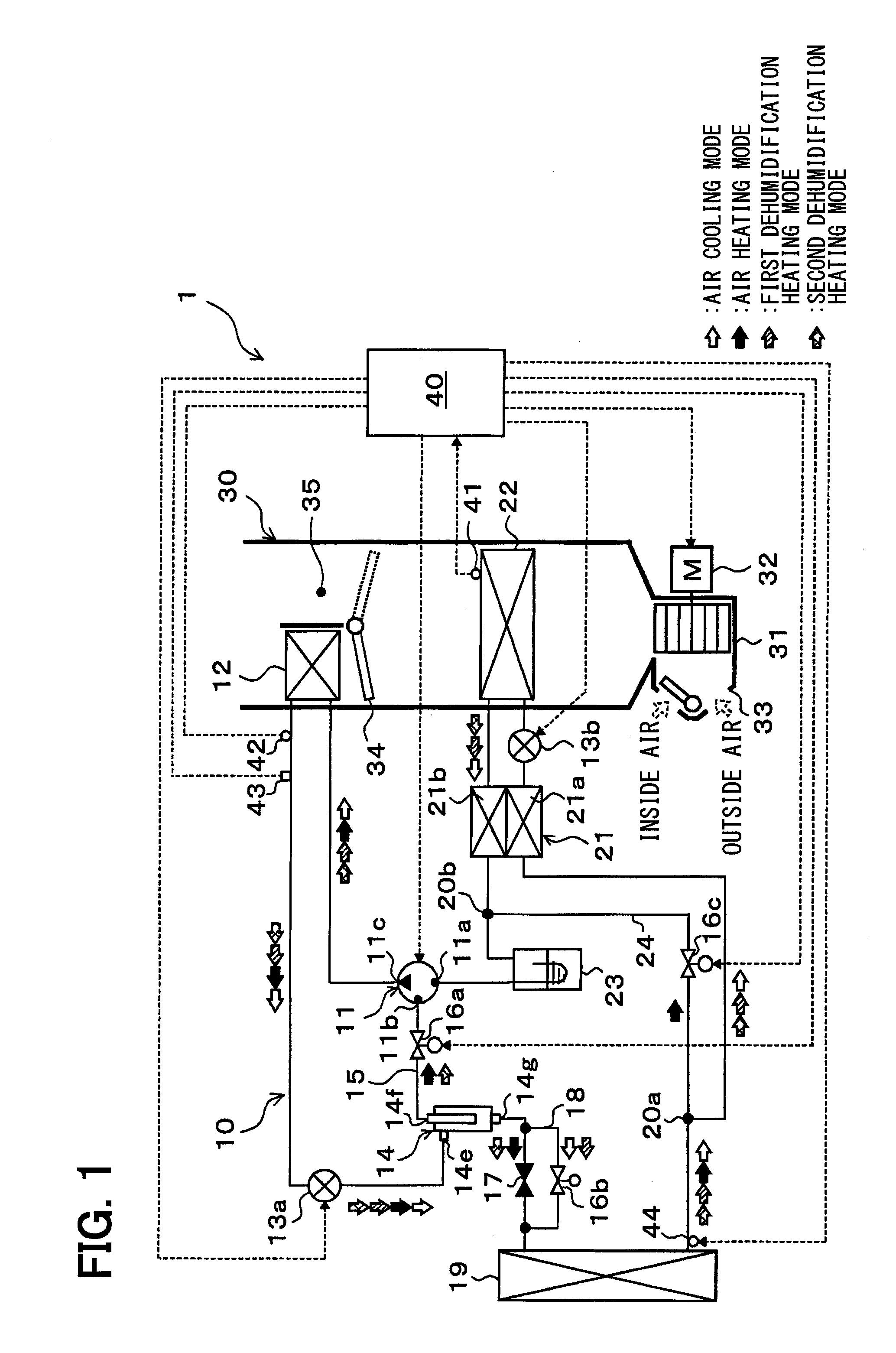
[0030]A first embodiment of the present disclosure will be described below with reference to FIGS. 1 to 7. In this embodiment, a refrigeration cycle device 10 is applied to a vehicle air conditioner 1 for a hybrid vehicle that can obtain the driving force for traveling from both the engine, or the internal combustion engine and an electric motor for traveling. The refrigeration cycle device 10 serves to cool or heat ventilation air to be blown into the vehicle interior as a space to be air-conditioned in the vehicle air conditioner 1.

[0031]The refrigeration cycle device 10 of this embodiment can be configured to switch among a refrigerant circuit for an air cooling mode of air-cooling of the vehicle interior by cooling the ventilation air, a refrigerant circuit for an air heating mode of air-heating of the vehicle interior by heating the ventilation air, and refrigerant circuits for first and second dehumidification heating modes of both air-heating and dehumidification of the vehic...

second embodiment

[0188]This embodiment will describe an example in which the structure of the refrigeration cycle device in the first embodiment is changed to that of a refrigeration cycle device 10a, as illustrated in the entire configuration diagram of FIG. 8.

[0189]Specifically, the refrigeration cycle device 10a of this embodiment employs, as the compressor 51, a single-stage boost electric compressor that rotatably drives a fixed displacement compression mechanism by the electric motor to compress the refrigerant drawn from a suction port 51a, to discharge the compressed refrigerant from a discharge port 51c. The number of revolutions (refrigerant discharge capacity) of the compressor 51 is controlled by a control signal output from the air conditioning controller 40 in the same way as that of the compressor 11 in the first embodiment.

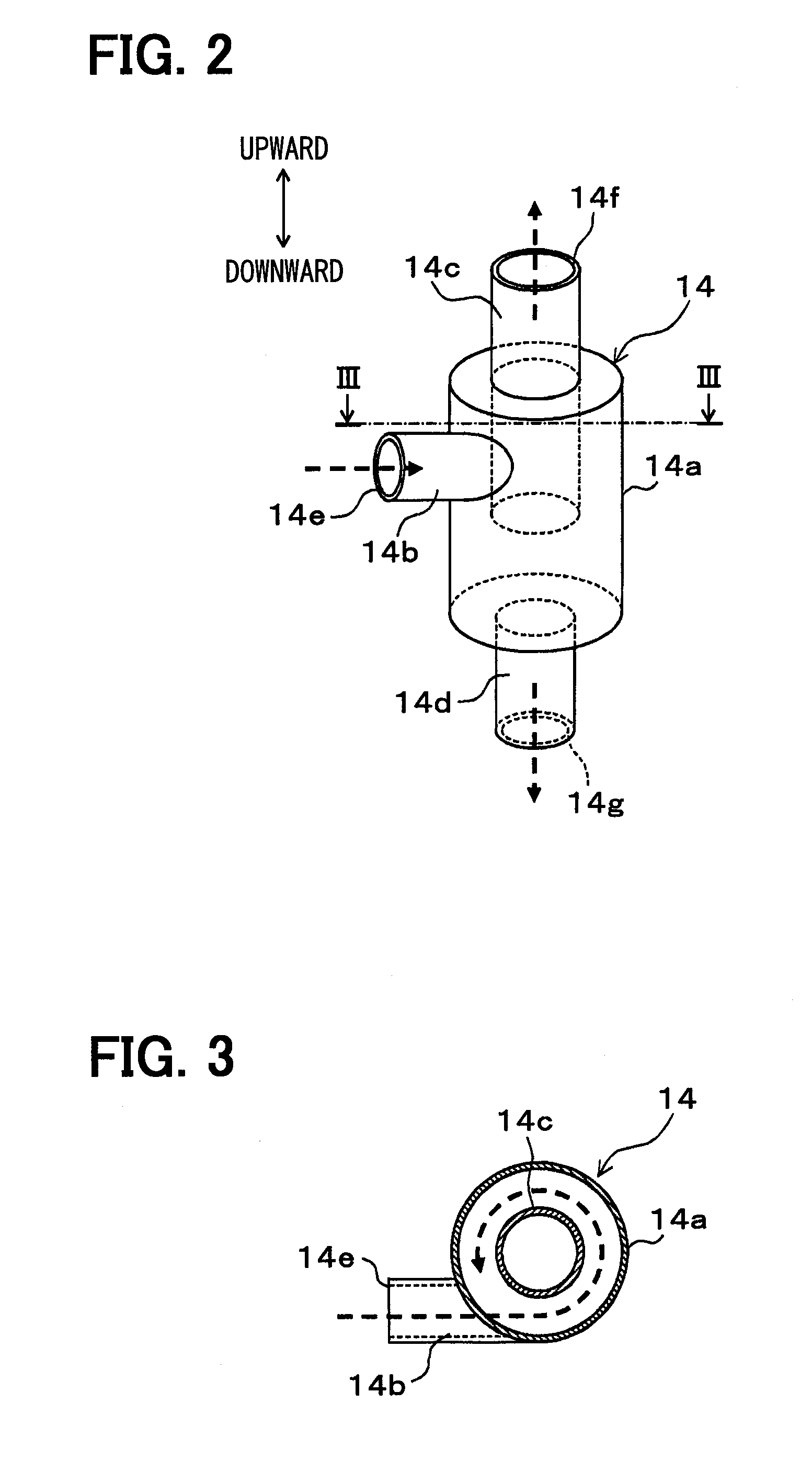
[0190]The gas-phase refrigerant passage 15 of this embodiment connects the gas-phase refrigerant outlet 14f of the gas-liquid separator 14 to the side of the sucti...

third embodiment

[0220]This embodiment will describe an example in which the structure of the refrigeration cycle device 10 in the first embodiment is changed to that of a refrigeration cycle device 10b, as illustrated in the entire configuration diagrams of FIG. 9.

[0221]Specifically, the refrigeration cycle device 10b of this embodiment abolishes the gas-phase refrigerant passage 15, the gas-phase refrigerant passage opening / closing valve 16a, and the intermediate fixed throttle 17 from the refrigeration cycle device 10a of the second embodiment. Further, in this embodiment, the gas-phase refrigerant outlet 14f of the gas-liquid separator 14 is closed. The structures of other components in the third embodiment are the same as those in the first embodiment.

[0222]Next, the operation of the above-mentioned structure according to this embodiment will be described below. The basic operation of the vehicle air conditioner 1 in this embodiment is substantially the same as that in the first embodiment. The...


PUM


Abstract

A refrigeration cycle device includes an interior condenser that exchanges heat between a high-pressure refrigerant and ventilation air to heat the ventilation air, an exterior heat exchanger that exchanges heat between outside air and the refrigerant downstream of the interior condenser, an interior evaporator that exchanges heat between a low-pressure refrigerant downstream of the exterior heat exchanger and the ventilation air before passing through the interior condenser, and an internal heat exchanger that exchanges heat between the refrigerant flowing out of the exterior heat exchanger and the refrigerant flowing out of the interior evaporator. The refrigeration cycle device further includes a gas-liquid separator that separates the refrigerant at a downstream side of the interior condenser into gas and liquid phase refrigerants. In a dehumidification heating mode of evaporating the refrigerant at the exterior heat exchanger, the liquid-phase refrigerant separated by the gas-liquid separator flows into the exterior heat exchanger.

Description

CROSS REFERENCE TO RELATED APPLICATION[0001]The application is based on a Japanese Patent Application No. 2013-087610 filed on Apr. 18, 2013, the contents of which are incorporated herein by reference in its entirety.FIELD OF THE INVENTION[0002]The present disclosure relates to refrigeration cycle devices to be applied to air conditioners that dehumidify a space to be air-conditioned.BACKGROUND ART[0003]Conventionally, as disclosed in Patent Document 1, a refrigeration cycle device has been proposed that is applied to air conditioners for vehicles and which can be configured to switch a refrigerant circuit. Specifically, the refrigeration cycle device is capable of switching among a refrigerant circuit for an air cooling mode of cooling the vehicle interior as a space to be air-conditioned, a refrigerant circuit for an air heating mode of heating the vehicle interior, and a refrigerant circuit for a dehumidification heating mode of heating and dehumidifying the vehicle interior.[000...

Claims


Application Information

Patent Timeline
Patent Type & Authority Applications(United States)
IPC IPC(8): B60H1/32F25B5/04
CPCB60H1/3223F25B5/04F25B2600/2513F25B2400/23F25B2341/0662F25B6/04B60H1/00921B60H1/3213F25B40/00F25B49/02F25B2600/2509F25B2700/195F25B2700/21163B60H1/3228F25B41/39
Inventor KOBAYASHI, HIROYUKIYAMADA, ATSUSHI
Owner DENSO CORP
Why Eureka
Try Eureka