
Fuel cell stack assembly - datum design for fuel cell stacking and collision protection

a fuel cell and stack assembly technology, applied in the direction of cell components, electrochemical generators, cell component details, etc., can solve the problems of increasing weight and complexity, facilitating subsequent stack disassembly, and exacerbated problems, so as to improve the resistance to inter-cell shifting, increase the resistance, and increase the resistance

Active Publication Date: 2016-03-10
GM GLOBAL TECH OPERATIONS LLC
View PDF2 Cites 40 Cited by
  • Summary
  • Abstract
  • Description
  • Claims
  • Application Information

AI Technical Summary

Benefits of technology

The present disclosure is about a fuel cell stack that has bipolar plates with a shaped edge that attach to an adjacent plate in a way that increases resistance to misalignment or movement between cells. This helps to reduce inter-cell shifting during a disruptive event. The method of assembling the fuel cell stack includes arranging cells along a stacking dimension and securing them within a housing to minimize inter-cell movement. The technical effect is improved performance and efficiency of the fuel cell stack.

Problems solved by technology

Such problems may be exacerbated by cold start conditions where thermally-induced contraction may reduce the Y-axis compressive retention load that was placed on the cells during stack assembly, as well as by reduced inter-cell friction brought about by the use of surface treatments or inserts that may have low coefficient of friction attributes.
The use of adhesives or supplemental support structure may tend to meliorate this problem to some degree, but in the process tends to add weight and complexity and—in the case of adhesives—is not conducive to subsequent stack disassembly for repair or diagnostic analysis.

Method used


Image

  • Fuel cell stack assembly - datum design for fuel cell stacking and collision protection
  • Fuel cell stack assembly - datum design for fuel cell stacking and collision protection
  • Fuel cell stack assembly - datum design for fuel cell stacking and collision protection

Examples


Embodiment Construction

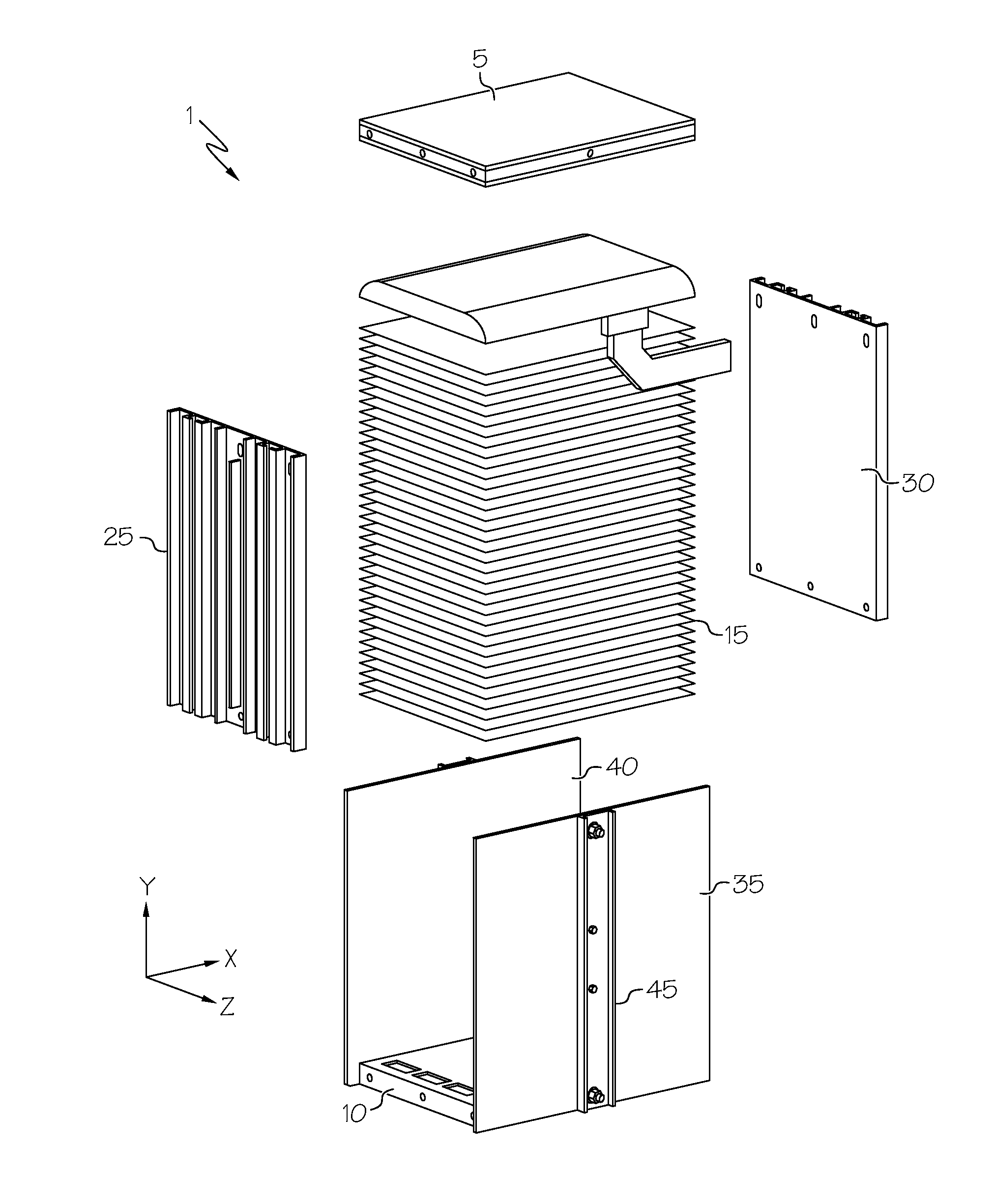
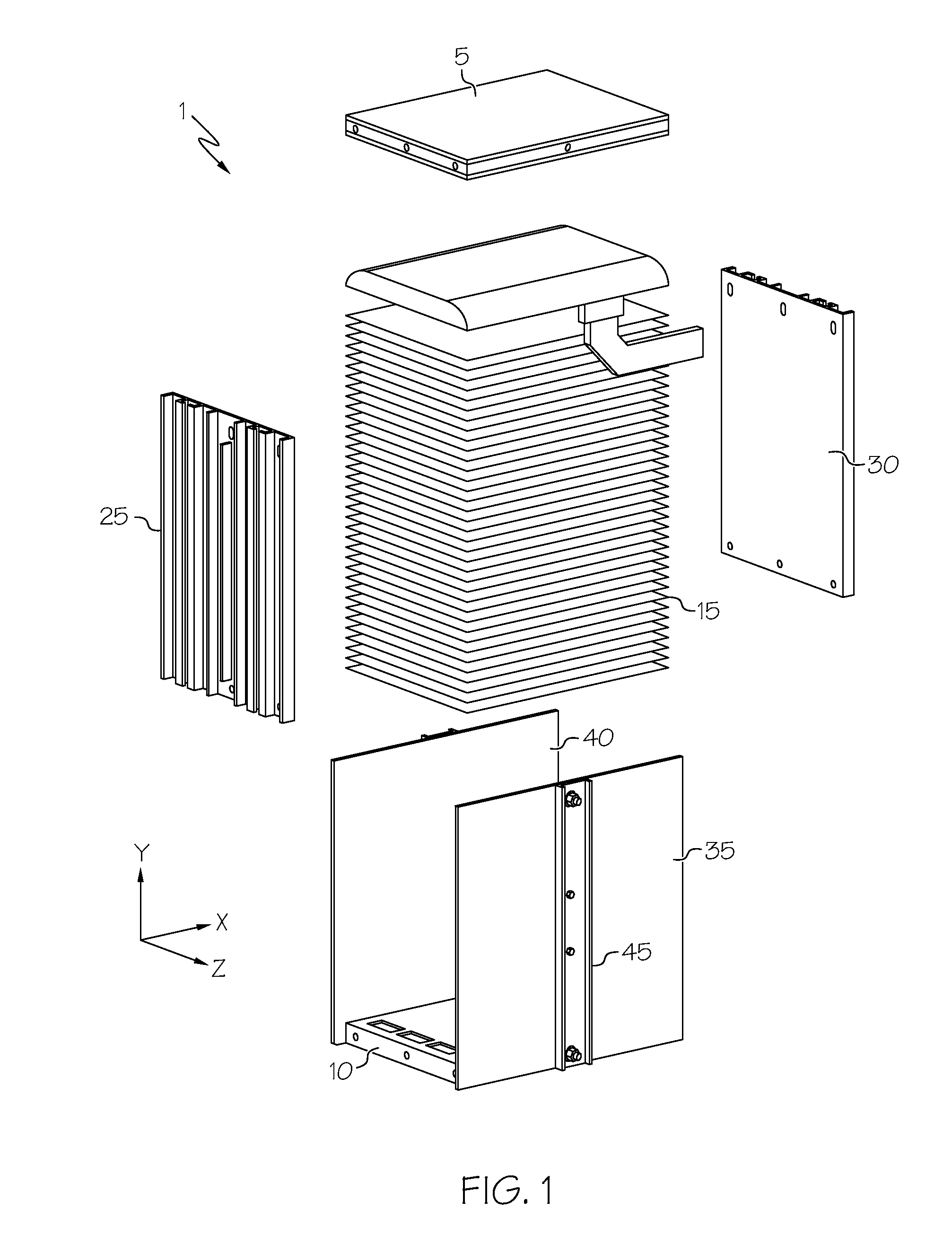
[0017]Referring first to FIG. 1, a fuel cell stack 1 is shown, and includes a dry end unit plate 5, a wet end unit plate 10 and a block of fuel cells 15 placed in stacking alignment between the end unit plates 5, 10. Although not shown in detail, each fuel cell 15 within the block generally includes the anode, cathode, and membrane arranged together to form the generally planar sandwich structure of the MEA that is pressed between a pair of the gas-permeable electrically conductive diffusion media that serve to both deliver reactants (i.e., H2 on the anode side of the MEA and O2 (typically in the form of air) on the cathode side of the MEA as well as collect electrical current that is catalytically produced at the anode and cathode. Within the present context, the stacking dimension that corresponds to the height of the assembled stack 1 is defined along the Y-axis as shown, although it will be appreciated by those skilled in the art that such is a matter of convenience, and that an...


PUM

PropertyMeasurementUnit
displacementsaaaaaaaaaa
thicknessaaaaaaaaaa

Abstract

A system and method for aligning and reducing the relative movement between adjacent fuel cells within a fuel cell stack. The inter-cell cooperation between fuel cells along a stacking dimension is enhanced by one or more datum placed along the edge of a bipolar plate that makes up a part of a cell-containing assembly. The datum is shaped along a thickness dimension that substantially coincides with the cell stacking dimension to promote a nested fit with a comparable datum on an adjacently-stacked bipolar plate. This nesting facilitates an interference fit that enhances the resistance to sliding movement between respective cells that may otherwise arise out of the occurrence of a significant acceleration along the dimension that defines the major surfaces of the plates, cells and their respective assemblies. In one form, the use of welding, bonding or related attachment of the datum to the plate promotes enhanced metallic support without the need for increasing the plate footprint and without having to overmold the datum directly onto the plate.

Description

BACKGROUND OF THE INVENTION[0001]The present disclosure relates generally to an improved design for assembling a fuel cell stack, as well as to distribute an acceleration load over a fuel cell stack to secure and maintain the relative position of the fuel cells within the stack after exposure to impacts and other high acceleration loads.[0002]A significant benefit to using fuel cells to convert a fuel into usable electricity via electrochemical reaction is that it is achieved without reliance upon combustion as an intermediate step. As such, fuel cells have several environmental advantages over internal combustion engines (ICEs) for propulsion and related motive applications. In a typical fuel cell—such as a proton exchange membrane or polymer electrolyte membrane (in either event, PEM) fuel cell—a pair of catalyzed electrodes are separated by an ion-transmissive medium (such as Nafion™) in what is commonly referred to as a membrane electrode assembly (MEA). The electrochemical reac...

Claims


Application Information

Patent Timeline
Patent Type & Authority Applications(United States)
IPC IPC(8): H01M8/24
CPCH01M2250/20H01M8/247H01M8/24H01M8/2465H01M8/2475H01M8/0247H01M8/0263H01M8/0271H01M2008/1095H01M8/2404Y02T90/40Y02E60/50
Inventor MARTINCHEK, DAVID A.THOMPSON, ROBERT C.HEINZMANN, MARTIN
Owner GM GLOBAL TECH OPERATIONS LLC
Learn More