

Submerged combustion burners, melters, and methods of use
a technology of submerged combustion and burners, which is applied in the direction of combustion types, manufacturing tools, lighting and heating apparatuses, etc., can solve the problems of high turbulence and foaming, rapid melting of glass batches, and common materials that are often insufficient to survive for extended periods of time in this environment, so as to reduce or eliminate the problems of known sc burners
- Summary
- Abstract
- Description
- Claims
- Application Information
AI Technical Summary
Benefits of technology
Problems solved by technology
Method used
Image

Examples
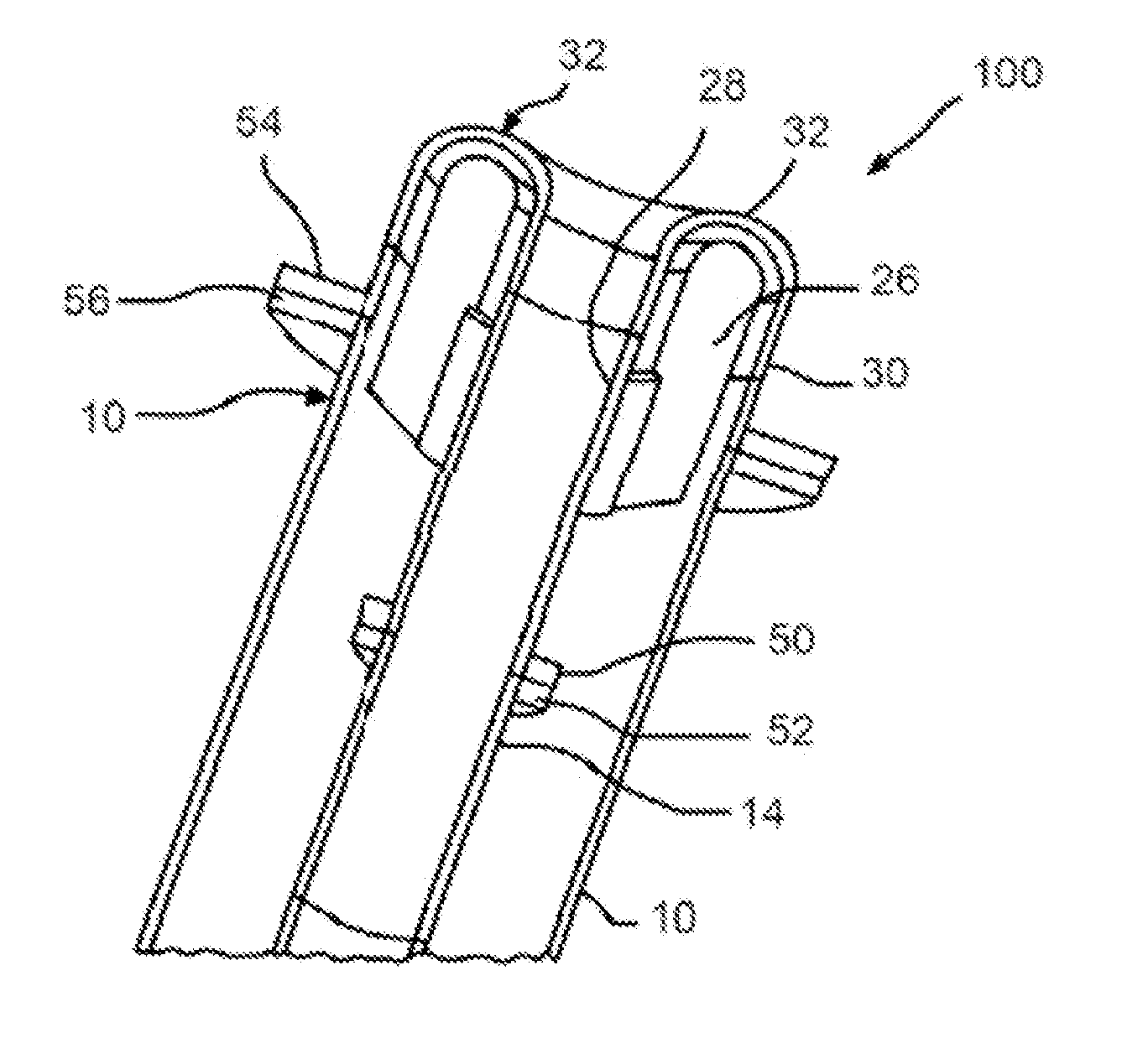
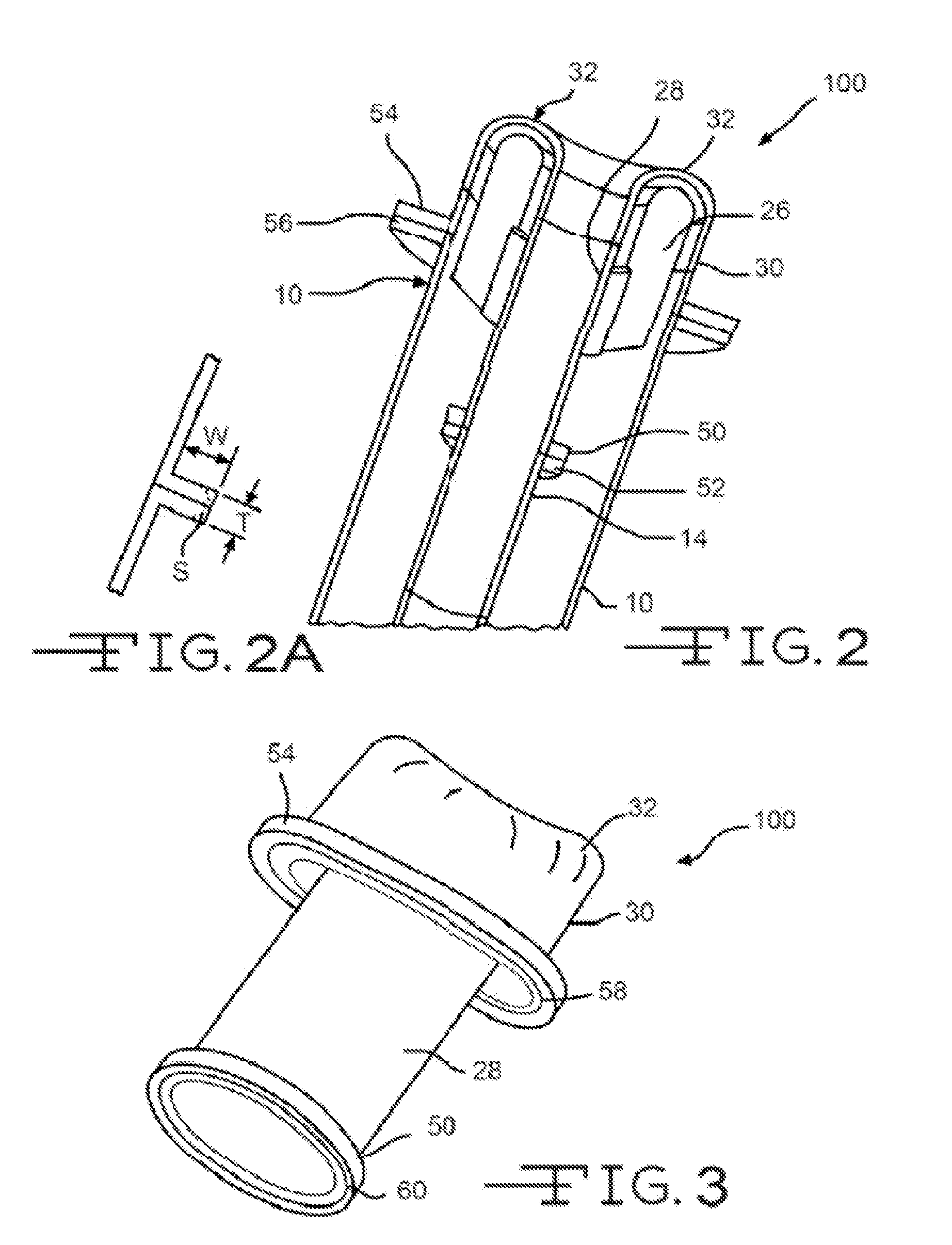
embodiment 100
[0071]FIG. 3 is a perspective view of the burner tip of embodiment 100, illustrating schematically the inclusion of deformable features 58, 60 on the faces of flange portions 50, 54. In the embodiment illustrated in FIG. 3, deformable features 58, 60 are raised linear areas of Pt / Rh or other corrosion / fatigue resistant material, but the format of the deformable areas may be any format that will deform the areas to form a seal, such as a plurality of discrete circular areas (“dots”), or dashed areas. Another embodiment, not illustrated, is to provide machined or molded non-deformable areas or regions on the mating faces of base metal flange portions 52, 56 (FIG. 2) and allow these non-deformable features to deform mating regions of corrosion / fatigue resistant flange portions 50, 54, it being understood that the hardness and / or ductility of the base metal are generally greater than the hardness and / or ductility of the corrosion / fatigue resistant material of the burner tip.
embodiment 200
[0072]Careful selection of gasket material is a feature of embodiment 200 illustrated in FIG. 4, which does not employ deformable features in the flange faces. In these embodiments, the gasket material used is resistant to oxygen attack, the required resistance level being greater as the percentage of oxygen in the oxidant stream increases. Suitable metallic gasket materials depend on the temperature, oxygen concentration, and expected life, but may include INCONEL (an alloy comprising 77 percent Ni, 15 percent Cr and 7 percent Fe) and titanium. Silica fabrics and silica tapes, such as those known under the trade designation MAXSIL (McAllister Mills, Inc., Independence, Va.), may be used.
embodiment 300
[0073]FIG. 5 illustrates schematically embodiment 300 employing the same or different braze materials 70 and 72 between flange portions 54, 56 and 50, 52, respectively. The braze materials may be independently selected from any metallic braze materials having a solidus temperature at least 10° C., preferably at least 20° C. greater than the burner tip temperature, cooled by flowing coolant and flowing combustion gases, oxidant and / or fuel. Some non-limiting examples are provided in Table 1 herein. In certain embodiments it may not be necessary that the braze material fill the entire width “W” of the flange joint or joints, however, those embodiments having 100 percent fill are exemplary embodiments.
PUM
| Property | Measurement | Unit |
|---|---|---|
| melt temperature | aaaaa | aaaaa |
| melt temperature | aaaaa | aaaaa |
| melt temperature | aaaaa | aaaaa |
Abstract
Description
Claims
Application Information