
Receiver system and method for receiver testing

a receiver and receiver technology, applied in the direction of receiver monitoring, instruments, measurement devices, etc., can solve the problems of difficult and expensive testing of millimeter wave systems, method is not very reliable, and vco's tend to be unstabl

Inactive Publication Date: 2016-03-17
NXP USA INC
View PDF0 Cites 43 Cited by
  • Summary
  • Abstract
  • Description
  • Claims
  • Application Information

AI Technical Summary

Benefits of technology

The present invention is a receiver system, a method for testing it, a radar system, and a vehicle. The technical effects of the invention include improved signal quality, better sensitivity, and reduced interference. These improvements can lead to better overall performance of the receiver system and increased accuracy of radar detection. The methods described herein can also be used to test and develop new receiver systems and radar systems.

Problems solved by technology

Testing of millimetre wave systems however is difficult and expensive.
This method is not very reliable as the high-frequency probe signals can be very sensitive to the characteristics of the transmission lines employed.
However, VCO's tend to be unstable.

Method used


Image

  • Receiver system and method for receiver testing
  • Receiver system and method for receiver testing
  • Receiver system and method for receiver testing

Examples


Embodiment Construction

[0013]Because the illustrated embodiments of the present invention may for the most part, be implemented using electronic components and circuits known to those skilled in the art, details will not be explained in any greater extent than that considered necessary as illustrated above, for the understanding and appreciation of the underlying concepts of the present invention and in order not to obfuscate or distract from the teachings of the present invention.

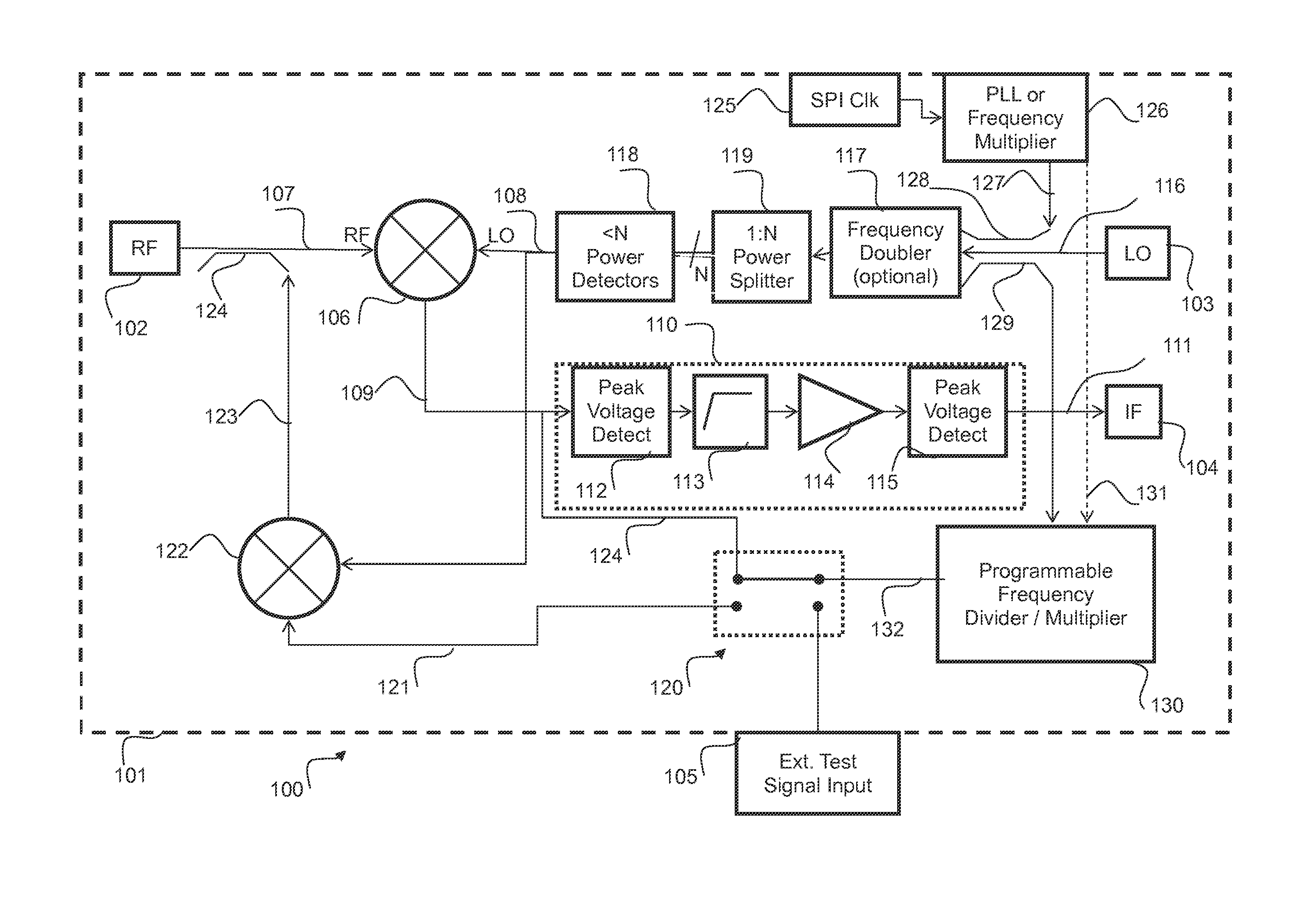
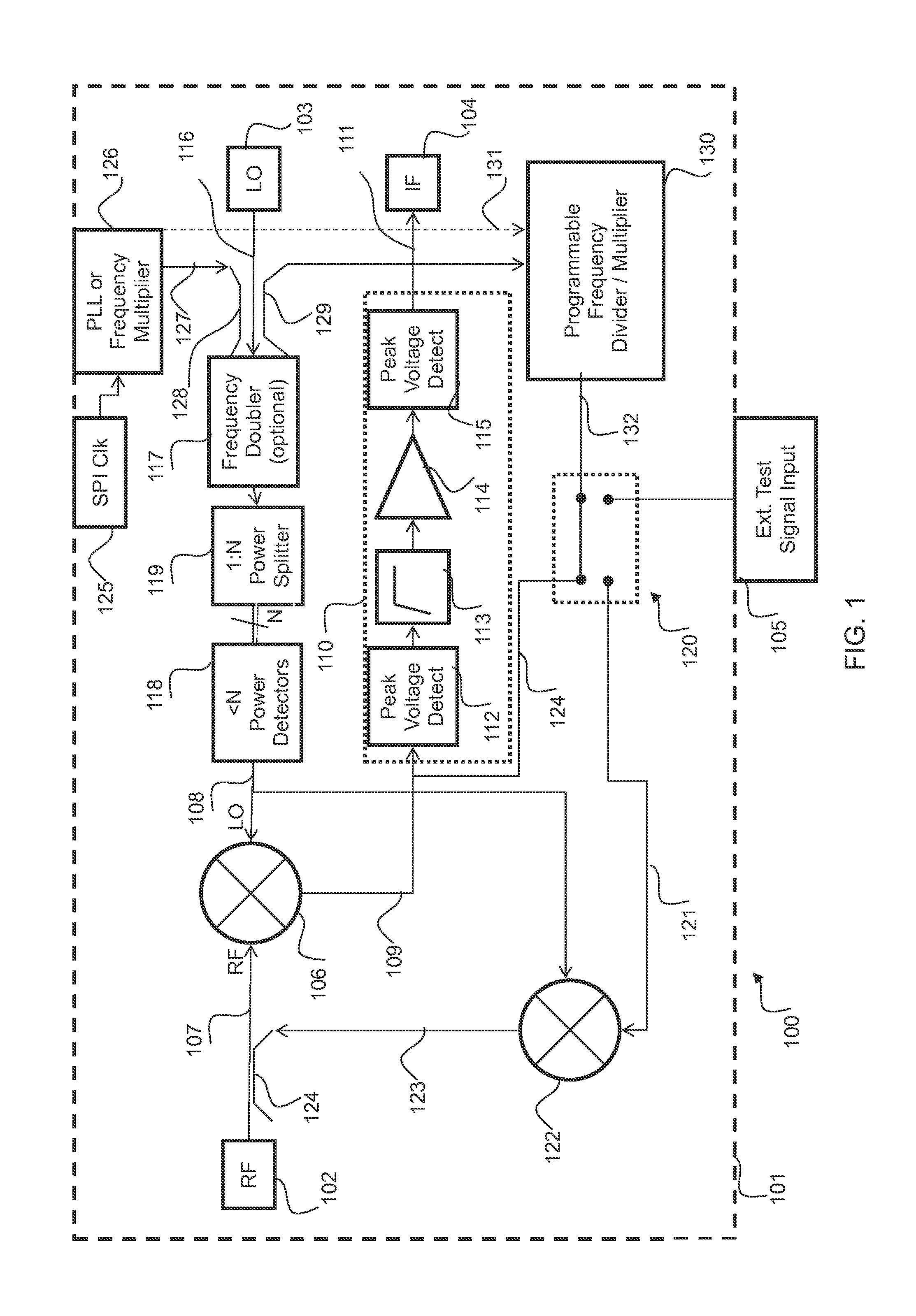
[0014]Referring now to FIG. 1 an example of a receiver system is indicated at 100 and may comprise an integrated circuit 101. The receiver system may include RF circuitry, baseband circuitry and a built in test circuitry. The receiver system in some embodiments may comprise a multichannel receiver system. In some embodiments, the integrated circuit 101 may comprise a package which may take any variety of forms such as for example, a plastic dual in-line package, ceramic dual in-line package, chip-scale package, lead-frame packag...


PUM


Abstract

A receiver system which may be implemented in an integrated circuit device and suitable for use in automotive radar systems such as collision avoidance systems, includes self test circuitry whereby a local oscillator test signal is generated by an on-board frequency multiplier and mixed in a down-conversion mixer with an RF test signal. The RF test signal is generated on the device by up-conversion of an externally generated low-frequency test signal with the local oscillator test signal. Baseband components may also be checked using test signals of suitable frequency divided down from the local oscillator test signal by a programmable frequency divider. This self test arrangement obviates any need for applying externally generated RF test signals to the IC device.

Description

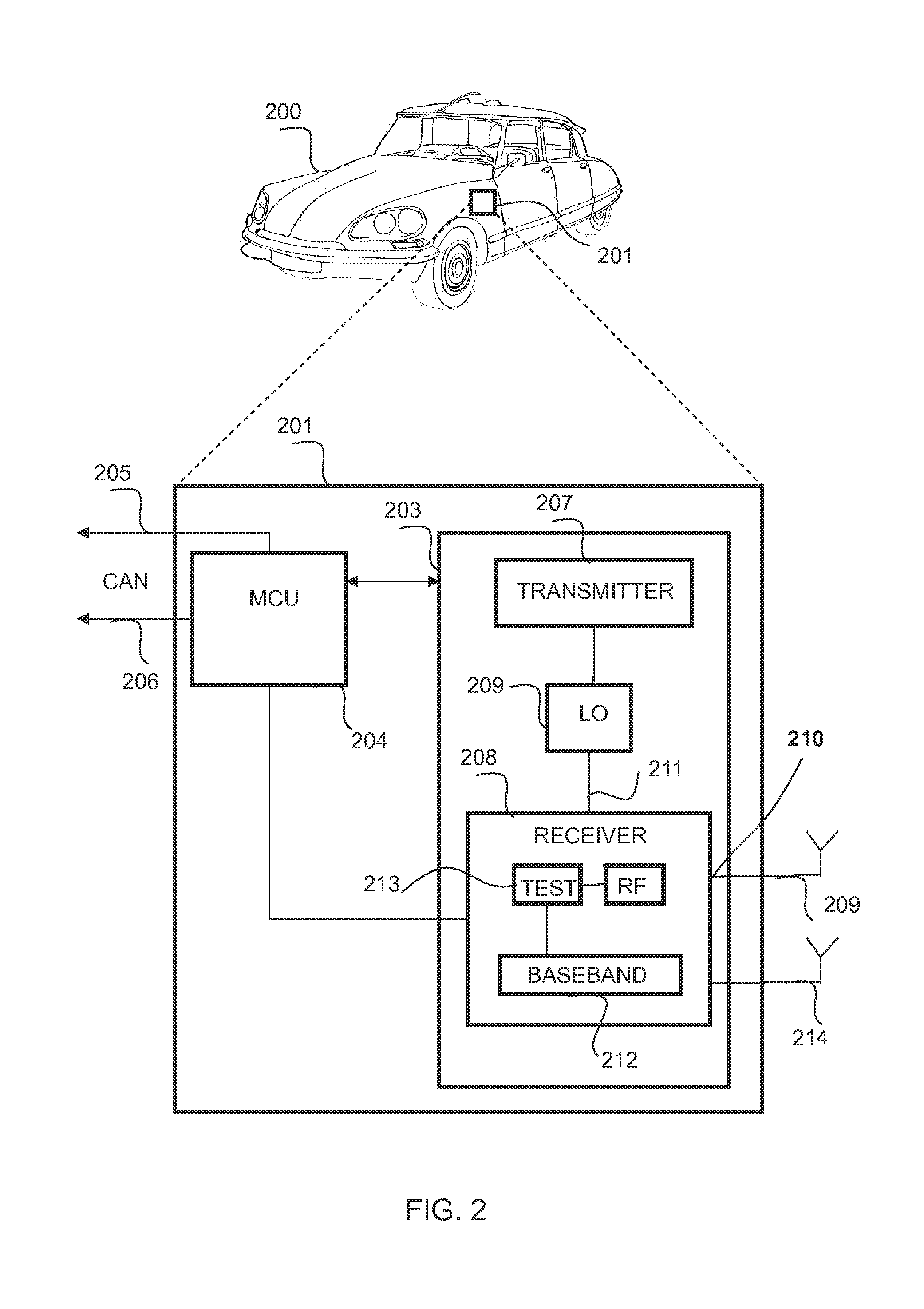
FIELD OF THE INVENTION[0001]This invention relates to a receiver system and a method for receiver testing and has particular, though not exclusive, applicability to radar receivers for vehicles.BACKGROUND OF THE INVENTION[0002]Millimetre wave radio frequency (RF) systems are finding increasing application in active safety systems for vehicles such as adaptive cruise control and collision warning systems. An increasing demand for such systems has led to a corresponding interest in integrating these RF systems on silicon and / or compound semiconductor-based integrated circuits rather than using discrete components. Silicon integration provides the possibility of manufacturing larger volumes of such systems at lower cost compared with discrete component systems or system based on compound semiconductors. Millimetre wave frequencies are generally defined to be between around 30-300 GHz with 77 GHz being a typical operating frequency for an automotive radar system. A typical radar receive...

Claims


Application Information

Patent Timeline
Patent Type & Authority Applications(United States)
IPC IPC(8): G01S7/40G01S13/931
CPCG01S7/4052G01S2007/406G01S13/931G01R31/2822H04B17/29G01S7/406
Inventor DEHLINK, BERNHARDGHAZINOUR, AKBARREUTER, RALF
Owner NXP USA INC
Learn More