

Catalyst and electrode catalyst layer, membrane electrode assembly, and fuel cell using the catalyst
Inactive Publication Date: 2016-03-17
NISSAN STEEL CHEM & MATERIAL CO LTD +1
View PDF7 Cites 14 Cited by
- Summary
- Abstract
- Description
- Claims
- Application Information
AI Technical Summary
Benefits of technology
The patent aims to improve the performance of a membrane electrode assembly in a fuel cell by providing an electrode catalyst layer that has a high contact ratio between the catalyst metal particles and the electrolyte, while also reducing the specific surface area and thus maintaining catalyst activity. This results in better power generation performance of the fuel cell.
Problems solved by technology
In general, such a polymer electrolyte fuel cell uses expensive metal catalyst represented by platinum (Pt) or a Pt alloy, which leads to high cost of the fuel cell.
Method used
View moreImage
Smart ImageViewing Examples

Examples
synthesis example 1
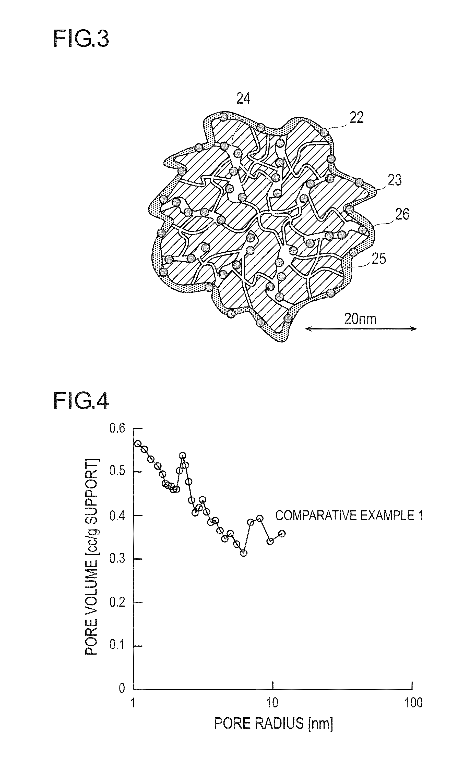
[0127]A support A having a pore volume of 1.56 cc / g, a mode radius of the pores of 1.65 nm, and a BET specific surface area of 1773 m2 / g was manufactured. Specifically, the support A was manufactured according to the method disclosed in WO 2009 / 075264 or the like.
synthesis example 2
[0128]As a support B, Ketjen Black EC300J (produced by Ketjen Black International Co., Ltd.) having a pore volume of 0.69 cc / g and a BET specific surface area of 790 m2 / g was prepared.
synthesis example 3
[0129]A support C having a pore volume of 2.16 cc / g, a mode radius of the pores of 2.13 nm, and a BET specific surface area of 1596 m2 / g was manufactured. Specifically, the support C was manufactured according to the method disclosed in JP-A-2009-35598 or the like.
Login to View More PUM
 Abstract
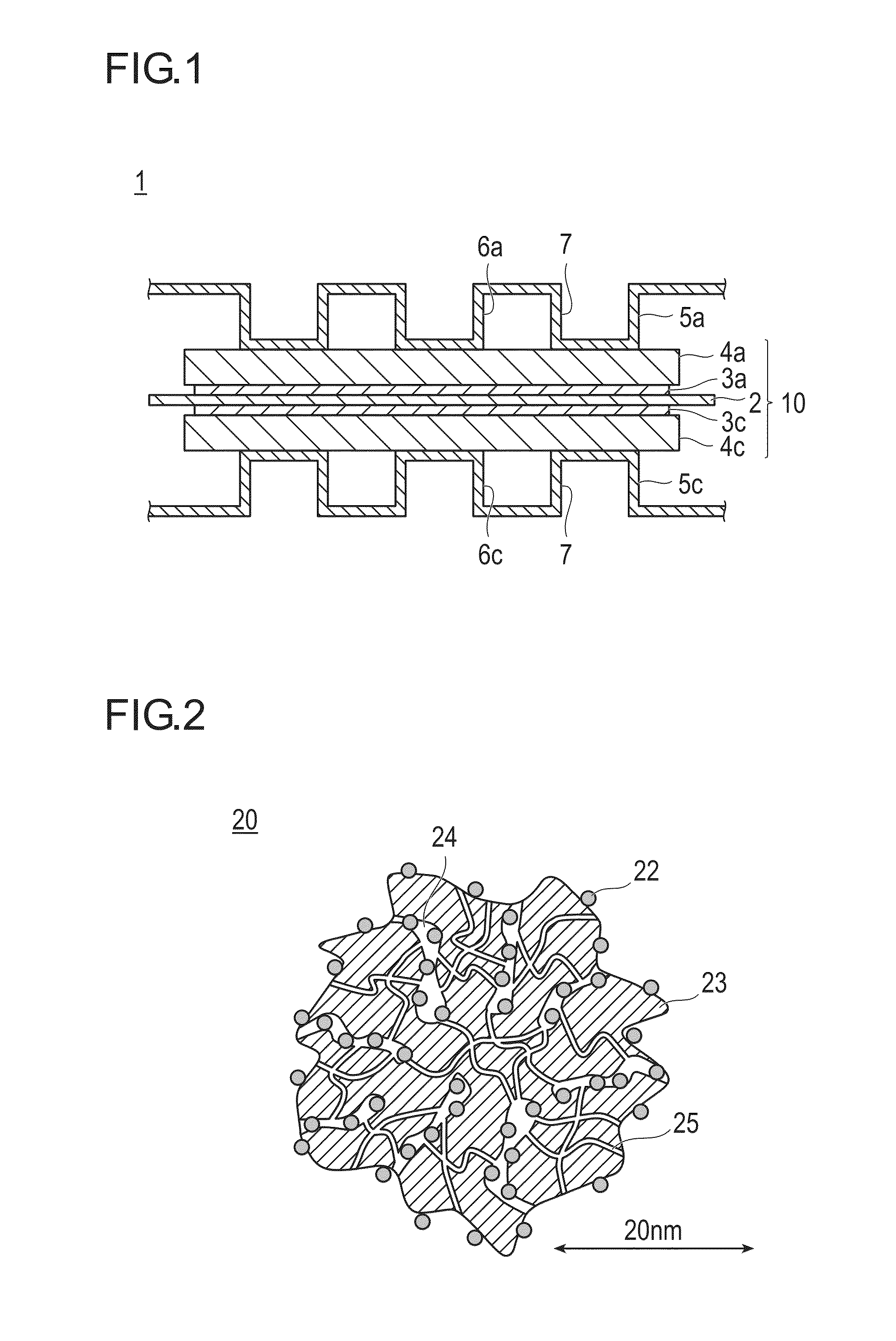
The object of the present invention is to provide a catalyst having an excellent catalyst activity.In the present invention, a catalyst is configured to include a catalyst support and a catalyst metal supported on the catalyst support, wherein a mode radius of pore distribution of pores of the catalyst is 1 nm or more and less than 5 nm, wherein the mode radius is equal to or less than an average particle radius of the catalyst metal, and wherein a pore volume of the pores is 0.4 cc / g support or more.
Description
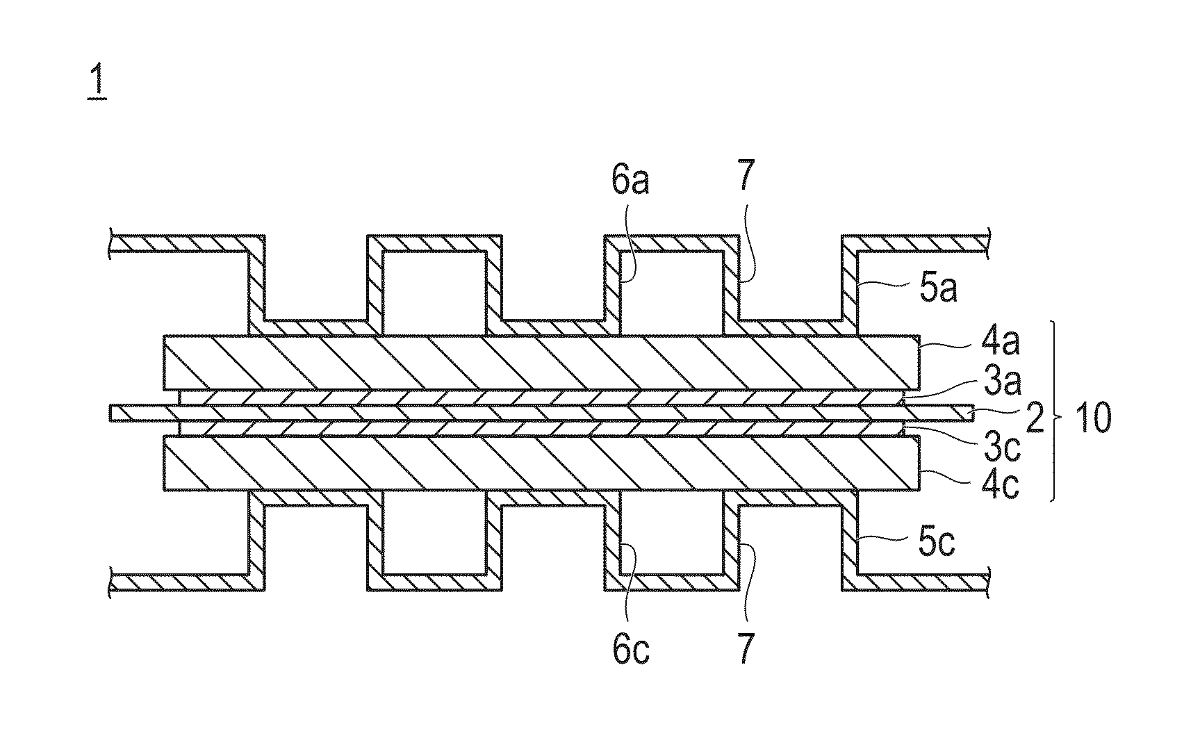
TECHNICAL FIELD[0001]The present invention relates to a catalyst, and particularly, to an electrode catalyst used for a fuel cell (PEFC) and an electrode catalyst layer, a membrane electrode assembly, and a fuel cell using the catalyst.BACKGROUND ART[0002]A polymer electrolyte fuel cell using a proton conductive solid polymer membrane operates at a low temperature in comparison to other types of fuel cells, for example, a solid oxide fuel cell or a molten carbonate fuel cell. For this reason, the polymer electrolyte fuel cell has been expected to be used as a power source for energy storage system or a driving power source for a vehicle such as a car, and practical uses thereof have been started.[0003]In general, such a polymer electrolyte fuel cell uses expensive metal catalyst represented by platinum (Pt) or a Pt alloy, which leads to high cost of the fuel cell. Therefore, development of techniques capable of lowering the cost of the fuel cell by reducing a used amount of noble me...
Claims
Login to View More Application Information
Patent Timeline
 IPC IPC(8): H01M4/92H01M8/02H01M8/10
CPCH01M4/92H01M2250/20H01M8/1004H01M8/02H01M4/8605H01M4/923H01M4/926H01M8/0234H01M2008/1095Y02E60/50Y02T90/40
InventorMASHIO, TETSUYAOHMA, ATSUSHITAKAHASHI, SHINICHIAKIZUKI, KEN
OwnerNISSAN STEEL CHEM & MATERIAL CO LTD