Apparatus for liquid degassing using coupling of swirling flow or centrifugal field and pressure gradient field

a technology of liquid degassing apparatus and swirling flow, which is applied in the direction of liquid degasification, chemistry apparatus and processes, and separation processes, etc., can solve the problems of reducing the efficiency of gas phase separation, increasing the diameter of gas columns, and other problems, so as to improve the gas discharge pressure, eliminate low removal efficiency problems, and optimize the structure of the outlet

Inactive Publication Date: 2016-03-24
EAST CHINA UNIV OF SCI & TECH
View PDF7 Cites 9 Cited by
  • Summary
  • Abstract
  • Description
  • Claims
  • Application Information

AI Technical Summary

Benefits of technology

[0017]The advantages of the current invention are: The present invention designs the structure of an inverted cone shaped outlet for gas phase which is inserted into the cavity of the swirling device. The present invention makes full use of the impact of pressure gradient in the cavity on the solubility of gas in liquid and combines the centrifugal field and the pressure gradient field to remove the gas entrained with liquid while the dissolved gas is removed under the inlet partial pressure. The present invention further op...

Problems solved by technology

Similarly, the flow rate of inlet is constant, and the entrainment of inlet gas is reduced, which also has the problem.
When the flow rate of the inlet increases or the inlet gas content increases, it will lead to the increase of gas column diameter, which results in the reduction of g...

Method used


Image

  • Apparatus for liquid degassing using coupling of swirling flow or centrifugal field and pressure gradient field
  • Apparatus for liquid degassing using coupling of swirling flow or centrifugal field and pressure gradient field
  • Apparatus for liquid degassing using coupling of swirling flow or centrifugal field and pressure gradient field

Examples


Embodiment Construction

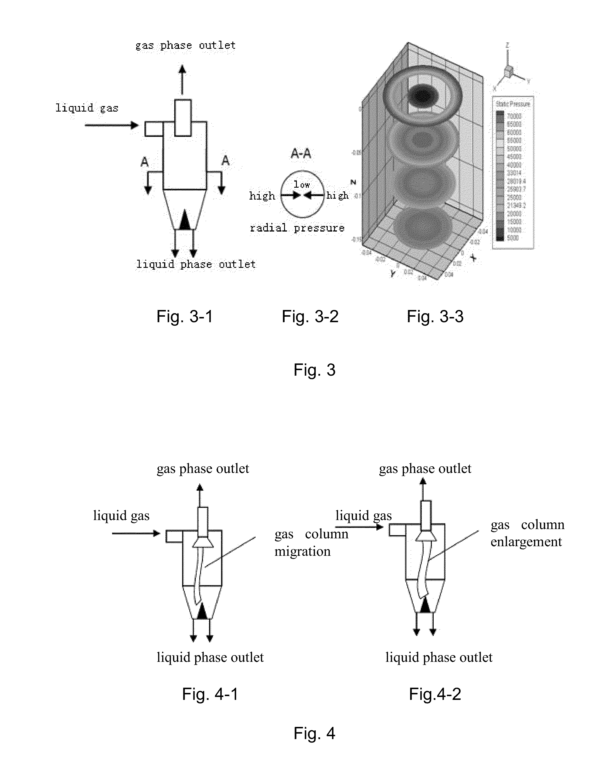
[0038]See FIG. 3. The inventor of the current invention discovers that the height of the column shaped cavity is 0.5-3 times the diameter of the column shaped cavity. There exists obvious pressure gradient in the radial cross section of the swirler, namely the pressure decreases inwards radially. According to Henry law, close to the height of the cross section, the pressure in the outside wall of the swirler is high whereas the central pressure is low. The gas dissolved under the pressure of the outside wall can migrate to the central position. To position the outlet for the gas phase in this location can further remove the gas dissolved in the pressure at the inlet. The swirling degassing technology combines the centrifugal field with the pressure gradient to remove the gas dissolved in the carrying liquid as well as in the entrance liquid under the partial pressure.

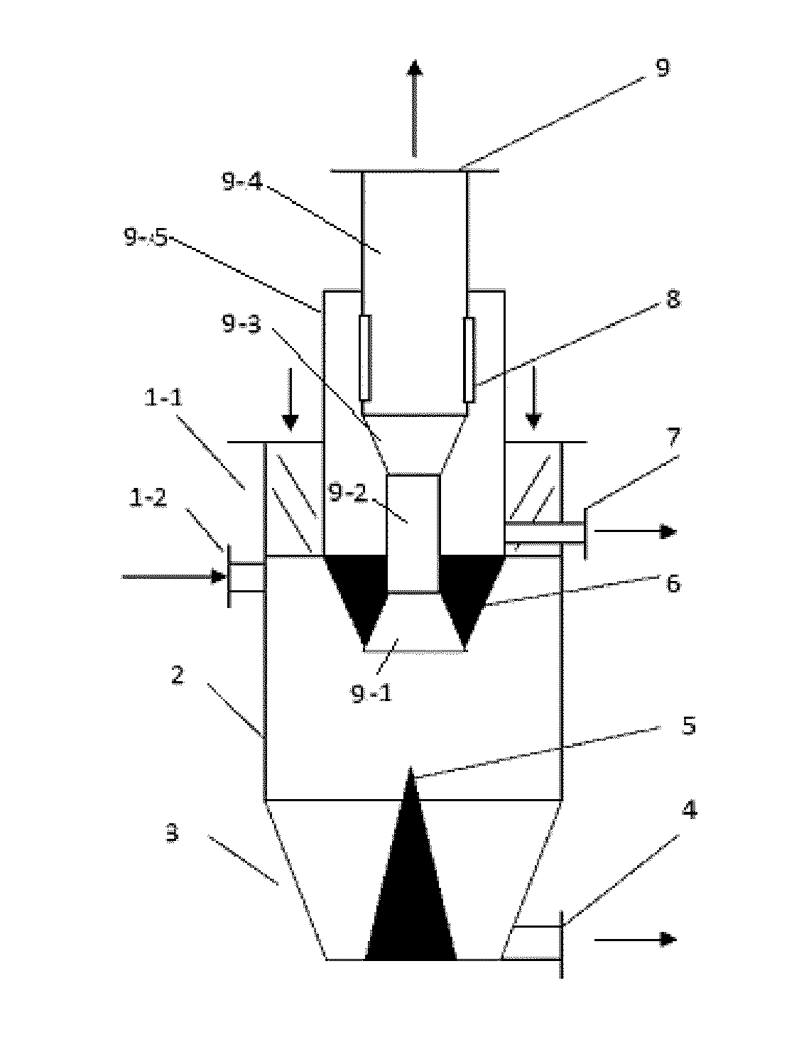
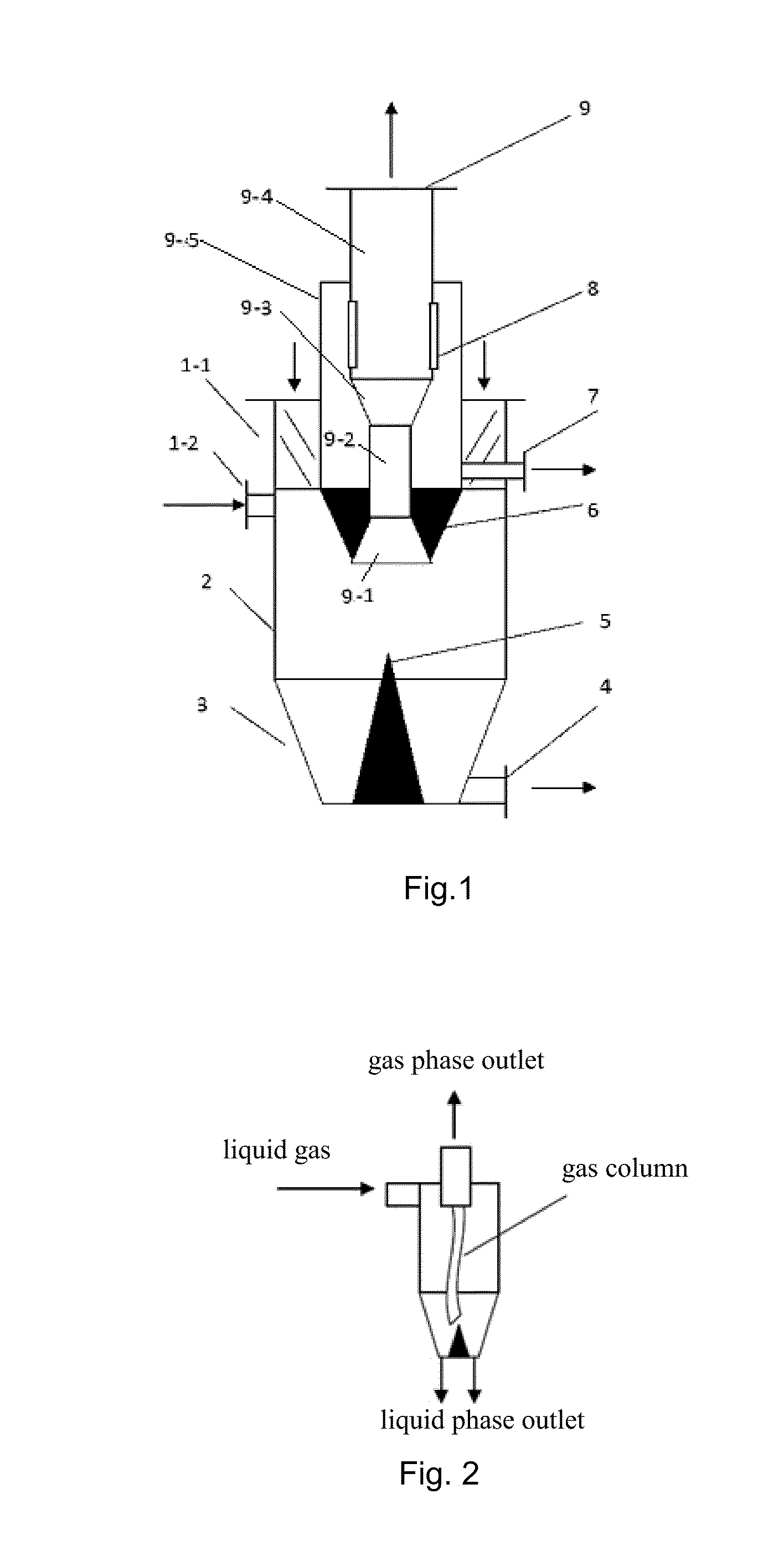
[0039]FIG. 1 is a schematic diagram of the structure of the device for high efficient liquid degassing by means of th...


PUM

PropertyMeasurementUnit
Pressureaaaaaaaaaa
Diameteraaaaaaaaaa
Solubility (mass)aaaaaaaaaa

Abstract

The present invention relates to a device for liquid degassing by means of the swirling or the centrifugal field coupled with the pressure gradient field. This device comprises a cavity. The cavity is furnished with an inlet for liquid gas, an outlet for gas phase and an outlet for gas liquid phase. The outlet for gas phase is inserted into the cavity through the upper surface of the cavity, wherein the depth of the insertion is around 0.1-3 times of the maximum diameter of the cavity. Specifically, the outlet for gas phase is realized through an overflow pipe with the diameter gradually increasing from the bottom to the top. The end of the overflow pipe is further furnished with a bell mouth. The advantages of the present invention are: The present invention designs the structure of an inverted cone shaped outlet for gas phase which is inserted into the cavity of the swirling device. The present invention makes full use of the impact of pressure gradient in the cavity on the solubility of gas in liquid and combines the centrifugal field and the pressure gradient field to remove the gas entrained with liquid while the dissolved gas is removed under the inlet partial pressure.

Description

TECHNICAL FIELD[0001]The present invention relates to a liquid degassing apparatus, in particular, relates to a device by means of the swirling of the centrifugal field coupled with the pressure gradient field to carry out the liquid degassing.TECHNICAL BACKGROUND[0002]There are large amounts of liquid degassing process in the petroleum chemical industry, coal chemical industry, food, water treatment, oil and other industries. Efficient and economical degassing technology plays an important role in the efficient, safe and long period operation of the device. Such as in the petrochemical industry, the release of dissolved gas from the liquid due to pipe pressure drop in the pressurized liquid delivery process cause air resistance, local corrosion and other issues. In the food industry, dissolved gases affect the purity of the products, and lead to the quality problems. The existence of dissolved oxygen in water treatment process is the main reason for the corrosion of the thermal equ...

Claims


Application Information

Patent Timeline
IPC IPC(8): B01D19/00
CPCB01D19/0052B01D19/0036B01D19/0057
Inventor YANG, QIANGXU, XIAOLU, HAOWANG, CHAOYANG
Owner EAST CHINA UNIV OF SCI & TECH
Why Eureka
Try Eureka