Eureka AIR delivers breakthrough ideas for toughest innovation challenges, trusted by R&D personnel around the world.

Heat/acoustic wave conversion component and heat/acoustic wave conversion unit

Active Publication Date: 2016-03-24
NGK INSULATORS LTD
View PDF0 Cites 5 Cited by
  • Summary
  • Abstract
  • Description
  • Claims
  • Application Information

AI Technical Summary

Benefits of technology

The present invention provides a heat / acoustic wave conversion component with a honeycomb structure that is more durable than existing components. The invention also includes a heat / acoustic wave conversion unit that includes the honeycomb structure and a heat exchanger. The heat / acoustic wave conversion component has specific values for certain physical attributes, such as hydraulic diameter, open frontal area, heat conductivity, and a ratio that result in improved durability and energy conversion efficiency. This allows for better conversion of heat into acoustic wave energy through a thermoacoustic effect.

Problems solved by technology

Patent Document 3, however, does not consider the durability of the component at all when it is used for a long time as a heat / acoustic wave conversion component.

Method used


Image

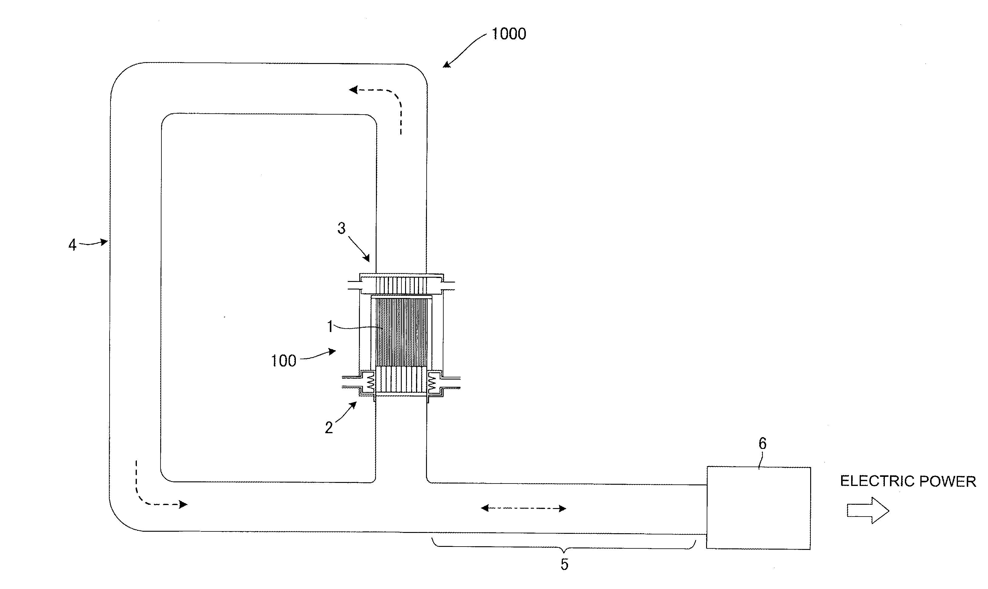
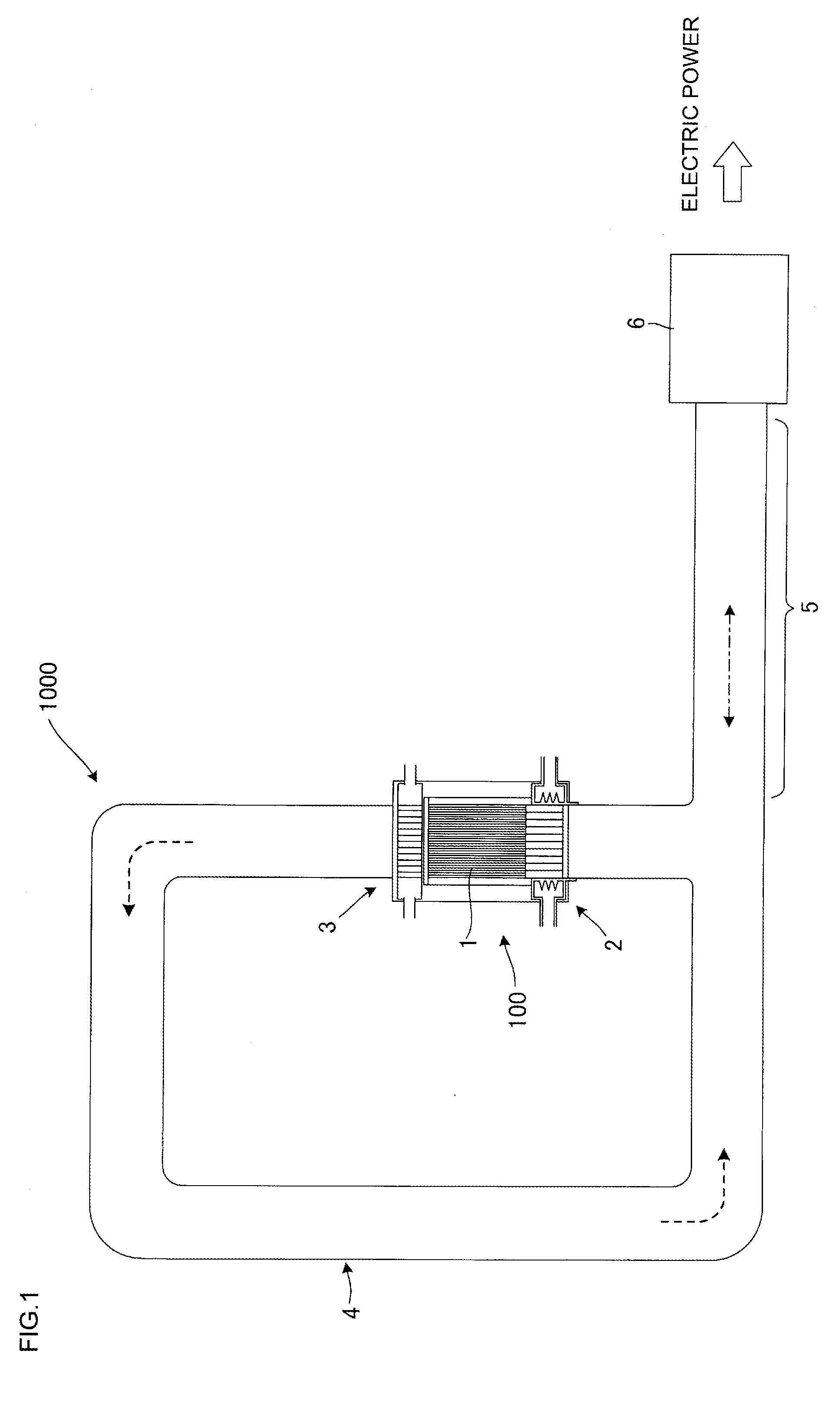
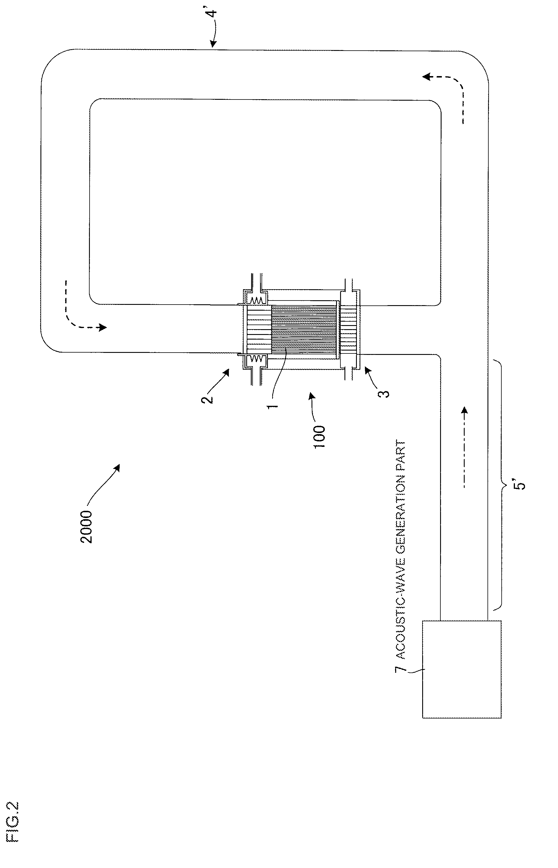
  • Heat/acoustic wave conversion component and heat/acoustic wave conversion unit
  • Heat/acoustic wave conversion component and heat/acoustic wave conversion unit
  • Heat/acoustic wave conversion component and heat/acoustic wave conversion unit

Examples


example 1

[0211]In Example 1, cordierite forming raw material was used as the ceramic raw material. Then 35 parts by mass of dispersing medium, 6 parts by mass of organic binder, and 0.5 parts by mass of dispersing agent were added to 100 parts by mass of the cordierite forming raw material, followed by mixing and kneading to prepare a kneaded material. The cordierite forming raw material used included 38.9 parts by mass of talc of 3 μm in average particle size, 40.7 parts by mass of kaolin of 1 μm in average particle size, 5.9 parts by mass of alumina of 0.3 μm in average particle size, and 11.5 parts by mass of boehmite of 0.5 μm in average particle size. Herein the average particle size refers to a median diameter (d50) in the particle distribution of each raw material.

[0212]Water was used as the dispersing medium. Hydroxypropylmethylcellulose was used as the organic binder. Ethylene glycol was used as the dispersing agent.

[0213]Next, the thus obtained kneaded material was extruded using a...

examples 2 , 3

Examples 2, 3 and Comparative Examples 1 to 3

[0228]Heat / acoustic wave conversion components as Examples 2, 3 and Comparative Examples 1 to 3 were manufactured by the same manufacturing method as that of the manufacturing method of Example 1 as stated above except that a die used for extrusion was different, where these heat / acoustic wave conversion components were different from Example 1 only in the values of parameters (hydraulic diameter HD and HD / L) relating to the hydraulic diameter HD of the cells among the fourteen types of parameters as stated above.

[0229]Then, the two experiments 1 and 2 similar to those for Example 1 were conducted for these Examples 2, 3 and Comparative Examples 1 to 3.

examples 12 , 13

Examples 12, 13 and Comparative Examples 10 to 14

[0236]Heat / acoustic wave conversion components as Examples 12, 13 and Comparative Examples 10 to 14 were manufactured by the same manufacturing method as that of the manufacturing method of Example 1 as stated above except that the length of extrusion was different during extrusion, where these heat / acoustic wave conversion components were different from Example 1 only in the values of parameters (length L, L / D and HD / L of segment) relating to the length L of the segment among the fourteen types of parameters as stated above.

[0237]Then, the two experiments 1 and 2 similar to those for Example 1 were conducted for these Examples 12, 13 and Comparative Examples 10 to 14.

[0238]The following Table 3 shows the experimental results of Examples 1 to 13 and Comparative Examples 1 to 14 as explained above, together with the values of parameters different from those of Example 1.

TABLE 3Segment lengthSegmentSegmentL / heat / acousticCellopenSegmentt...


PUM


Abstract

A heat / acoustic wave conversion component includes a plurality of monolithic honeycomb segments each including a partition wall that defines a plurality of cells extending between both end faces, and the plurality of monolithic honeycomb segments each mutually converts heat exchanged between the partition wall and the working fluid in the cells and energy of acoustic waves resulting from oscillations of the working fluid. In the heat / acoustic wave conversion component including the plurality of honeycomb segments each being monolithic configured, hydraulic diameter HD of the cells is 0.4 mm or less, open frontal area of the honeycomb segments is 60% or more and 93% or less, heat conductivity of the honeycomb segments is 5 W / mK or less, and a ratio HD / L of the hydraulic diameter HD to the length L of the honeycomb segment is 0.005 or more and less than 0.02.

Description

[0001]The present application is an application based on JP 2014-192022 filed on Sep. 19, 2014 with Japan Patent Office, the entire contents of which are incorporated herein by reference.BACKGROUND OF THE INVENTION[0002]1. Field of the Invention[0003]The present invention relates to heat / acoustic wave conversion components and heat / acoustic wave conversion units. More particularly, the present invention relates to a heat / acoustic wave conversion component to convert heat and acoustic-wave energy mutually, and a heat / acoustic wave conversion unit including a heat / acoustic wave conversion component and a heat exchanger.[0004]2. Description of the Related Art[0005]Recently society as a whole has been becoming more and more interested in effective use of energy resources, and so various techniques to reuse energy have been developed on a trial basis. Among them, an energy recycling system attracts attention because the acquisition rate (energy efficiency) of the energy acquired is high....

Claims


Application Information

Patent Timeline
IPC IPC(8): F03G7/00
CPCF03G7/00F02G1/0435F02G2243/54F03G7/002F25B9/145F25B2309/1402
Inventor MIYAIRI, YUKIOMIWA, SHINICHIDEGUCHI, YUJIMORI, TERUYOSHIHAMATSUKA, KAZUHIKOSUENOBU, HIROYUKIHIRONAGA, MASAYUKIKUMAZAWA, KAZUHIKONODA, NAOMI
Owner NGK INSULATORS LTD
Why Eureka
Eureka Blog
Learn More