

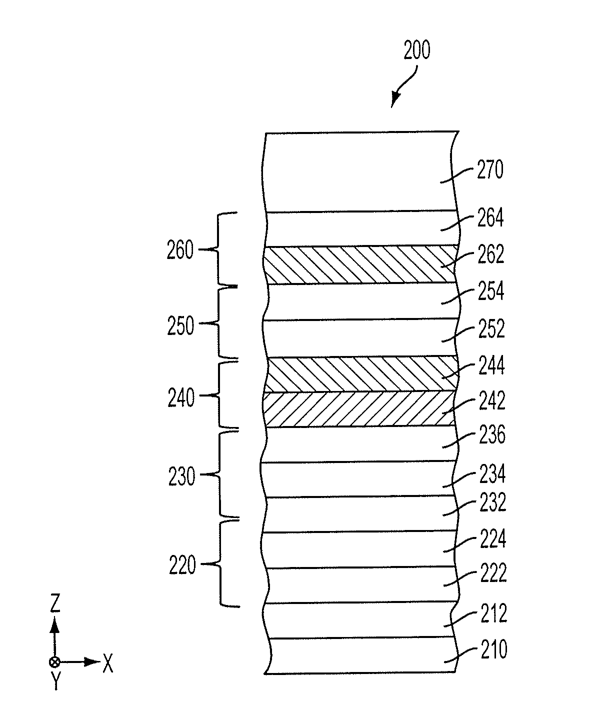
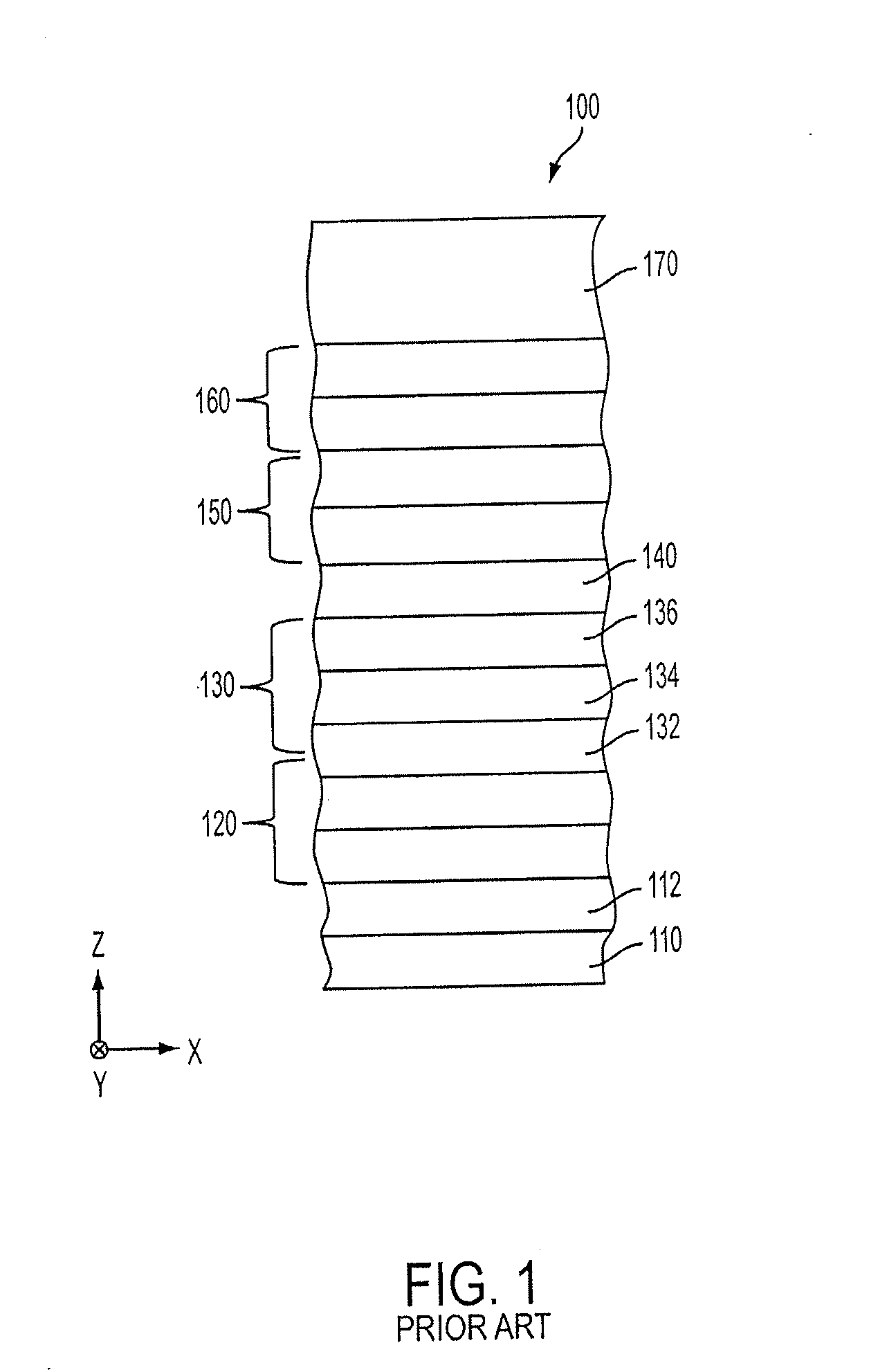
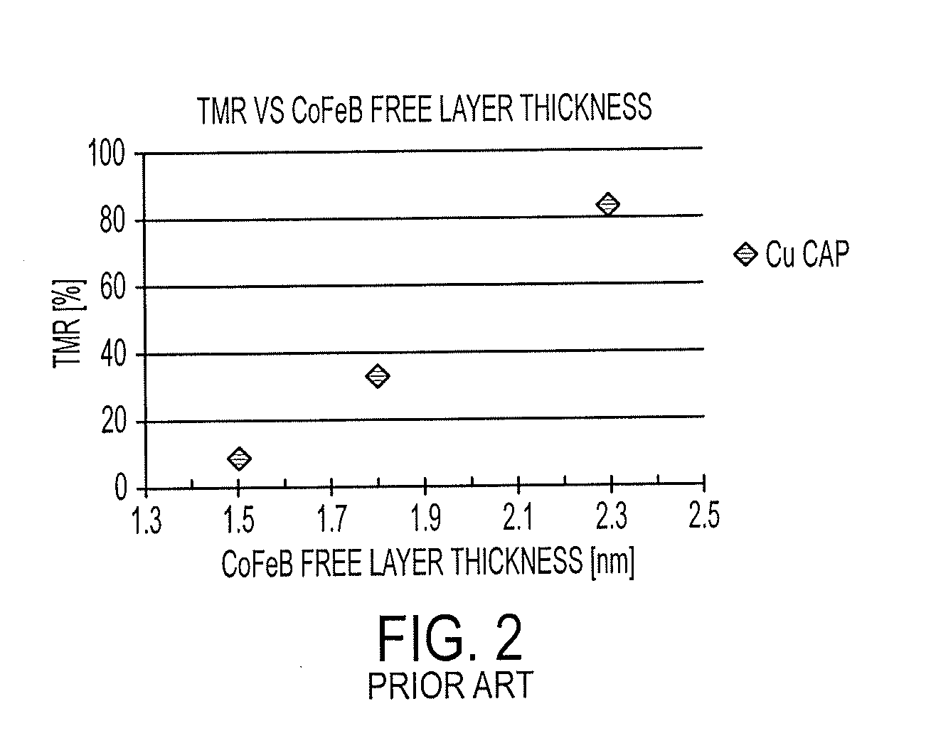
Magnetic tunnel junction structure for MRAM device
a tunnel junction and magnetic random access technology, applied in solid-state devices, magnetic bodies, instruments, etc., can solve the problems of inability to implement this technique/design, insufficient non-magnetic conductor layers in conventional mtj designs to obtain high tunneling magnetoresistance value (“tmr”), and achieve low resistance. , improve the tmr and switching characteristics of the mtj
- Summary
- Abstract
- Description
- Claims
- Application Information
AI Technical Summary
Benefits of technology
Problems solved by technology
Method used
Image

Examples
Embodiment Construction
[0035]A magnetic tunnel junction (“MTJ”) layer stack is disclosed herein. Each of the features and teachings disclosed herein can be utilized separately or in conjunction with other features and teachings. Representative examples utilizing many of these additional features and teachings, both separately and in combination, are described in further detail with reference to the attached drawings. This detailed description is merely intended to teach a person of skill in the art further details for practicing preferred aspects of the present teachings and is not intended to limit the scope of the claims. Therefore, combinations of features disclosed in the following detailed description may not be necessary to practice the teachings in the broadest sense, and are instead taught merely to describe particularly representative examples of the present teachings.
[0036]In the following description, for purposes of explanation only, specific nomenclature is set forth to provide a thorough und...
PUM
 Abstract
Description
Claims
Application Information