Preparation method of reference layer of magnetic tunnel junction, preparation method of magnetic tunnel junction

A magnetic tunnel junction and reference layer technology, applied in the manufacture/processing of electromagnetic devices, magnetic field controlled resistors, etc., can solve problems such as surface damage of the reference layer, eliminate damage or defects, improve overall performance, and improve TMR value Effect

Active Publication Date: 2021-07-13
CETHIK GRP +1
View PDF6 Cites 0 Cited by
  • Summary
  • Abstract
  • Description
  • Claims
  • Application Information

AI Technical Summary

Problems solved by technology

[0006] The main purpose of the present invention is to provide a method for preparing a reference layer of a magnetic tunnel junction and a method for preparing a magnetic tunnel junction, so as to solve the problems of damage and defects on the surface of the reference layer treated with plasma in the prior art

Method used


Image

  • Preparation method of reference layer of magnetic tunnel junction, preparation method of magnetic tunnel junction
  • Preparation method of reference layer of magnetic tunnel junction, preparation method of magnetic tunnel junction
  • Preparation method of reference layer of magnetic tunnel junction, preparation method of magnetic tunnel junction

Examples


preparation example Construction

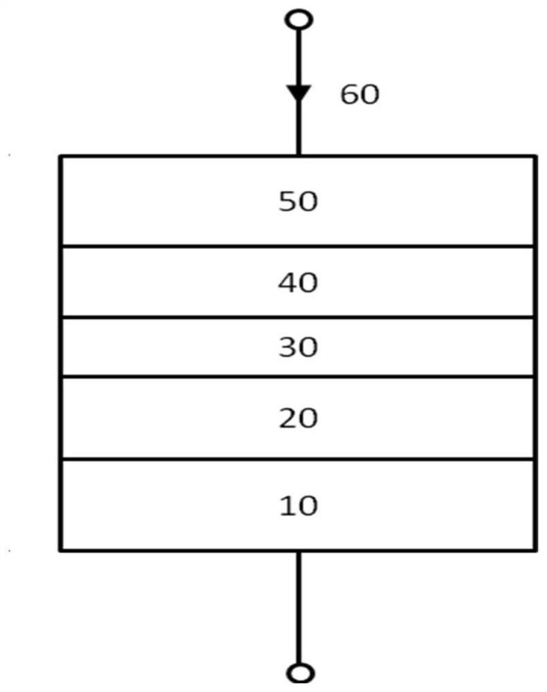
[0044] Preferably, the preparation method of the above-mentioned magnetic tunnel junction includes: setting a reference layer 20 on the buffer layer 10 using any of the above-mentioned preparation methods; setting a tunneling barrier layer 30 on the reference layer 20; setting a tunneling barrier layer 30 on the a free layer 40 ; and a protective layer is provided on the free layer 40 . The set buffer layer 10 can promote the formation of a relatively good crystal texture of the reference layer 20 grown thereon, and the protective layer 50 can protect the functional structure of the entire magnetic tunnel junction from water vapor pollution and oxidation.

[0045] The above-mentioned buffer layer 10 and protective layer 50 can be set by deposition methods, such as magnetron sputtering method, the specific setting conditions can refer to the prior art, and will not be repeated here. Preferably, the material for forming the buffer layer 10 includes Ta, Ti, TaN, TiN, Cu, Ag, Au, ...

Embodiment approach 1

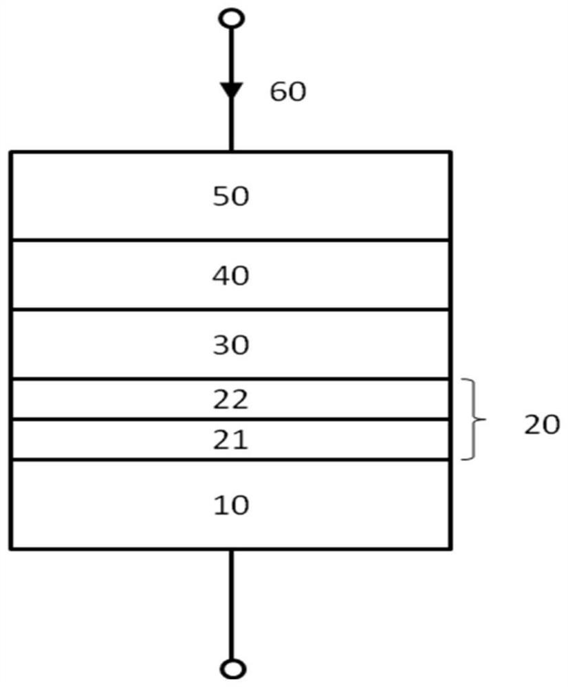
[0054] Embodiment 1: Deposit the first ferromagnetic pinned layer 221; perform plasma treatment on the first ferromagnetic pinned layer 221; perform annealing treatment on the first ferromagnetic pinned layer 221 after plasma treatment; A nonmagnetic interlayer 23 is deposited on the first ferromagnetic pinned layer 221 ; and a second ferromagnetic pinned layer 222 is deposited on the nonmagnetic interlayer 23 .

Embodiment approach 2

[0055] Embodiment 2: depositing the first ferromagnetic pinned layer 221; depositing the non-magnetic intermediate layer 23 on the first ferromagnetic pinned layer 221; depositing the second ferromagnetic pinned layer 222 on the non-magnetic intermediate layer 23 ; performing plasma treatment on the second ferromagnetic pinned layer 222 ; and performing annealing treatment on the second ferromagnetic pinned layer 222 after the plasma treatment.


PUM

PropertyMeasurementUnit
thicknessaaaaaaaaaa
thicknessaaaaaaaaaa
thicknessaaaaaaaaaa

Abstract

The invention provides a preparation method of a reference layer of a magnetic tunnel junction and a preparation method of the magnetic tunnel junction. The preparation method of the reference layer of the magnetic tunnel junction comprises adopting a deposition process to set each film layer of the reference layer, using plasma to treat one or more layers in each film layer, and treating one of the film layers after plasma treatment Layer or layers are annealed. Use annealing treatment to perform in-situ heat treatment on one or more film layers after plasma treatment, thereby reducing or eliminating damage or defects that may be caused by plasma treatment, improving the surface characteristics of the reference layer, and then improving the magnetic properties of the reference layer. The overall performance of the tunnel junction, such as increasing the TMR value of the magnetic tunnel junction and reducing its RA value.

Description

technical field [0001] The present invention relates to the field of spin transfer torque magnetic random access memory (STT-MRAM), in particular to a method for preparing a reference layer of a magnetic tunnel junction and a method for preparing a magnetic tunnel junction. Background technique [0002] STT-MRAM is a potential and revolutionary general-purpose storage technology, which can directly use spin-polarized current to drive the magnetic moment reversal of nanomagnets to complete information writing. It integrates the high storage density of DRAM, the fast read and write capability of SRAM, the non-volatility, low power consumption and high stability of Flash. In addition, it has the advantage of unlimited use; compared with traditional MRAM, It has better scalability, lower write information current, especially, it is compatible with the most advanced semiconductor process. [0003] The core device in STT-MRAM is a magnetic tunnel junction (MTJ), which mainly incl...

Claims


Application Information

Patent Timeline
Patent Type & Authority Patents(China)
IPC IPC(8): H01L43/12H01L43/08
CPCH10N50/10H10N50/01
Inventor 刘鲁萍简红蒋信
Owner CETHIK GRP
Why Eureka
Try Eureka