Constant current-constant voltage circuit

a constant current and voltage circuit technology, applied in the direction of electric variable regulation, process and machine control, instruments, etc., can solve the problems of increased cost and poor input stability, and achieve the effects of reducing the rise of drain-to-source voltage, reducing the amount of input voltage, and low resistance voltage elements

Inactive Publication Date: 2016-03-31
DENSO CORP
View PDF3 Cites 2 Cited by
  • Summary
  • Abstract
  • Description
  • Claims
  • Application Information

AI Technical Summary

Benefits of technology

[0012]By providing the fifth transistor, it may be possible to suppress the rise of the voltage at the intermediate node and the rise of the drain-to-source voltage of the first transistor which is not saturation-connected, due to the rise of the supply voltage. It may also be possible to suppress the rise of the drain-to-source voltage of the third transistor which is not saturation-connected. Therefore, a voltage higher than the constant voltage generated at the intermediate node is not applied to the first transistor through the fifth transistor which are coupled between the intermediate node and the second power source line, allowing the employment of a low withstand voltage element.
[0013]According to the configuration of the present disclosure, the drain-to-source voltages of the first transistor and the second transistor approach a close value within

Problems solved by technology

Accordingly, the increase in cost is caused.
It

Method used


Image

  • Constant current-constant voltage circuit
  • Constant current-constant voltage circuit
  • Constant current-constant voltage circuit

Examples


first embodiment

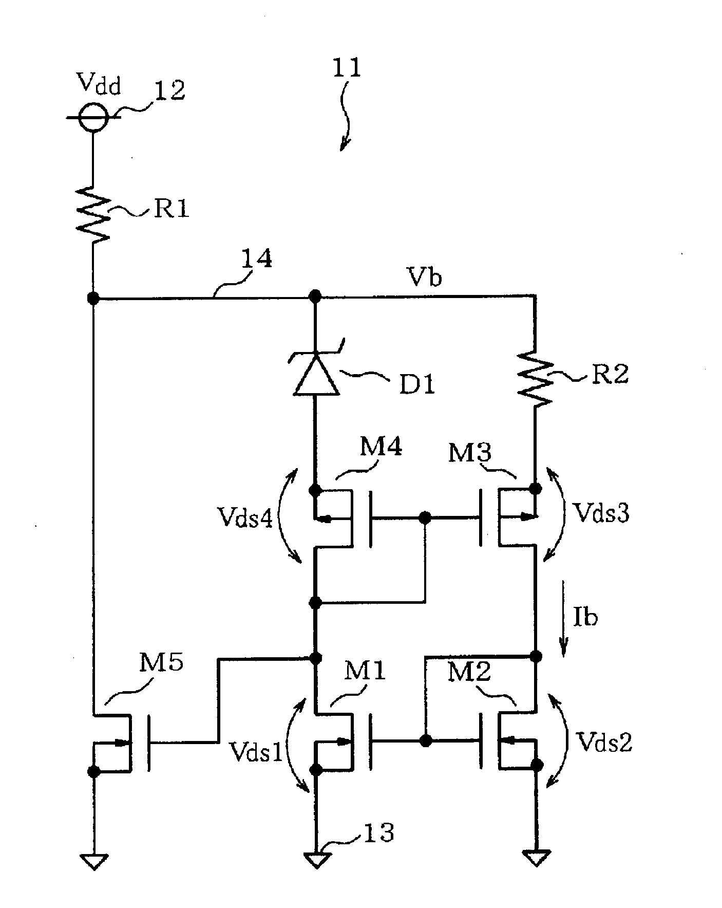
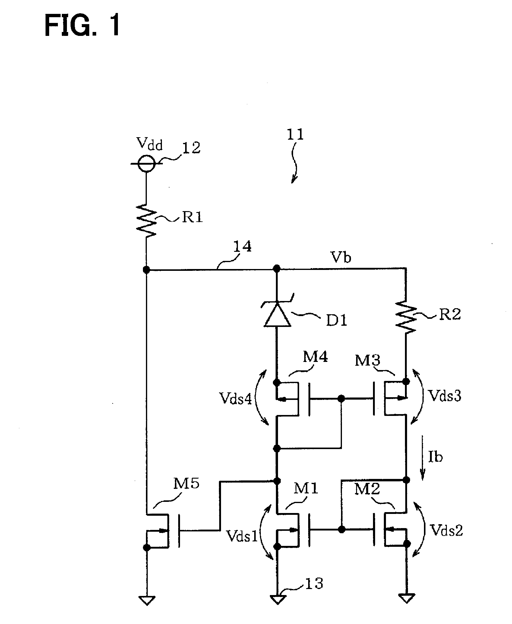
[0021]With reference to FIG. 1 and FIG. 2, a first embodiment of the present disclosure will be explained. A constant current-constant voltage circuit 11 illustrated in FIG. 1 is used for an electronic control apparatus mounted to a hybrid vehicle or an electric vehicle that run by driving a motor by the power supplied from a power drive battery. Between a first power source line 12 and a second power source line 13 (a ground line), a supply voltage Vdd of about 200V to 300V is applied from the battery.

[0022]The constant current-constant voltage circuit 11 generates a constant voltage Vb at an intermediate node 14 having an intermediate potential of the first power source line 12 and the second power source line 13, and flows a constant drain current Ib (also referred to as a constant current Ib) through a second transistor M2. A first resistor R1 is coupled between the first power source line 12 and the intermediate node 14. Between the intermediate node 14 and the second power sou...

second embodiment

[0035]A second embodiment is explained with reference to FIG. 3. A constant current-constant voltage circuit 21 is different from the constant current-constant voltage circuit 11 illustrated in FIG. 1 in that a Zener diode D2 is included between the intermediate node 14 and the drain of the fifth transistor M5. Other configuration is the same. The Zener diode D2 corresponds to a second constant voltage element according to the present disclosure. In the constant current-constant voltage circuit 11, the highest constant voltage Vb is applied to the fifth transistor M5 among the transistors M1-M5. According to the present embodiment, the drain-to-source voltage of the fifth transistor M5 decreases by the Zener voltage Vz (D2) of the Zener diode D2. Therefore, it may be possible to further reduce the element withstand voltage of the fifth transistor M5. In addition, it may be possible to obtain the same operation and effect as those in the first embodiment.

third embodiment

[0036]A third embodiment is explained with reference to FIG. 4. Instead of including the second resistor R2 and the Zener diode D1 between the intermediate node 14 and the transistors M3 and M4, a constant current-constant voltage circuit 31 includes the second resistor R2 and the Zener diode D1 between the sources of the transistors M2 and M1, and the second power source line 13. Furthermore, in order to equalize the source potential of the first transistor M1 and the source potential of the fifth transistor M5, a Zener diode D3 is coupled between the source of the fifth transistor M5 and the second power source line 13. Other configurations are the same as the constant current-constant voltage circuit 11 illustrated in FIG. 1. The Zener diode D3 corresponds to the third constant voltage element according to the present disclosure.

[0037]Since the threshold voltages of the transistors M1, M2, and M5 are mutually equal, it is only necessary to set the Zener voltages of the Zener diod...


PUM


Abstract

A constant current-constant voltage circuit includes a first resistor; a first transistor that is an N-channel type; a second transistor; a third transistor that is a P-channel type; a fourth transistor that is a P-channel type; a fifth transistor; a second resistor; and a first constant voltage element. The second resistor is coupled between the intermediate node and a source of the third transistor and the first constant voltage element is coupled between a source of the second transistor and the second power source line. A bias is set up and a source potential of the first transistor is equal to a source potential of the fifth transistor.

Description

CROSS REFERENCE TO RELATED APPLICATION[0001]The application is based on Japanese Patent Application No. 2013-150556 filed on Jul. 19, 2013, the disclosure of which is incorporated herein by reference.TECHNICAL FIELD[0002]This disclosure is related to a constant current-constant voltage circuit configured by a FET.BACKGROUND ART[0003]In recent years, a hybrid vehicle and an electric vehicle that run by driving a motor by the power supplied from a battery have been put in practical use. In connection with the motorization of a vehicle, the necessity for a control circuit that receives and operates at a high voltage increases. When the control circuit is configured so as to directly operate with a high supply voltage, an element having a high withstand voltage is required. In order to manufacture a semiconductor device (IC) including a high withstand voltage element, it is necessary to prepare a manufacturing process different from a manufacturing process of a low withstand voltage ele...

Claims


Application Information

Patent Timeline
IPC IPC(8): G05F3/26
CPCG05F3/262G05F3/18G05F3/24
Inventor IMURA, TAKASHI
Owner DENSO CORP
Why Eureka
Try Eureka