Solid electrolytic capacitor

a technology of electrolytic capacitors and solids, which is applied in the direction of electrolytic capacitors, fixed capacitors, fixed capacitor details, etc., can solve the problems of self-alignment properties degraded to the board to be soldered, and achieve the effect of sufficient welding strength

Active Publication Date: 2016-03-31
TOKIN CORP
View PDF19 Cites 3 Cited by
  • Summary
  • Abstract
  • Description
  • Claims
  • Application Information

AI Technical Summary

Benefits of technology

[0009]In the capacitor of Patent Literature 2, there is a possibility of providing an increased area of the mounting portion and improving an occupying volume efficiency of the capacitor element since the terminal portion of the anode terminal extends on the capacitor element side. However, there is a restriction to an increase in the mounting area because the rise portion is formed by raising a cut-in portion with a rectangular shape, resulting in self-alignment property with a board to be soldered being degraded.
[0010]The invention provides a solid electrolytic capacitor that has an improved ability of self-alignment in mounting the capacitor on a board and a sufficient welding strength between an anode wire and an anode terminal.
[0012]In an embodiment of this invention, in a main surface of an upright portion of an anode terminal, a length of an edge of the upright portion on an anode wire side is longer than a length of an edge of the upright portion on a mounting portion side. Accordingly, a mounting area to a board may be sufficiently ensured and a self-alignment property of the solid electrolytic capacitor in mounting on the board may be achieved.
[0013]In an embodiment, the length of the edge on the anode wire side may be set longer, and hence the solid electrolytic capacitor may employ anode wires having various shapes.
[0014]Moreover, in the main surface, the length of the edge on the anode wire side is longer than a width of the anode wire connected to the upright portion, and hence a welding strength between the anode terminal and the anode wire may be obtained. Further, a sufficient welding strength may be obtained also when a flat plate-like anode wire having a wider width is used.
[0020]As described above, it is possible to obtain the solid electrolytic capacitor that has the self-alignment property in mounting and the sufficient welding strength between the anode wire and the anode terminal.

Problems solved by technology

However, there is a restriction to an increase in the mounting area because the rise portion is formed by raising a cut-in portion with a rectangular shape, resulting in self-alignment property with a board to be soldered being degraded.

Method used


Image

  • Solid electrolytic capacitor
  • Solid electrolytic capacitor
  • Solid electrolytic capacitor

Examples


first embodiment

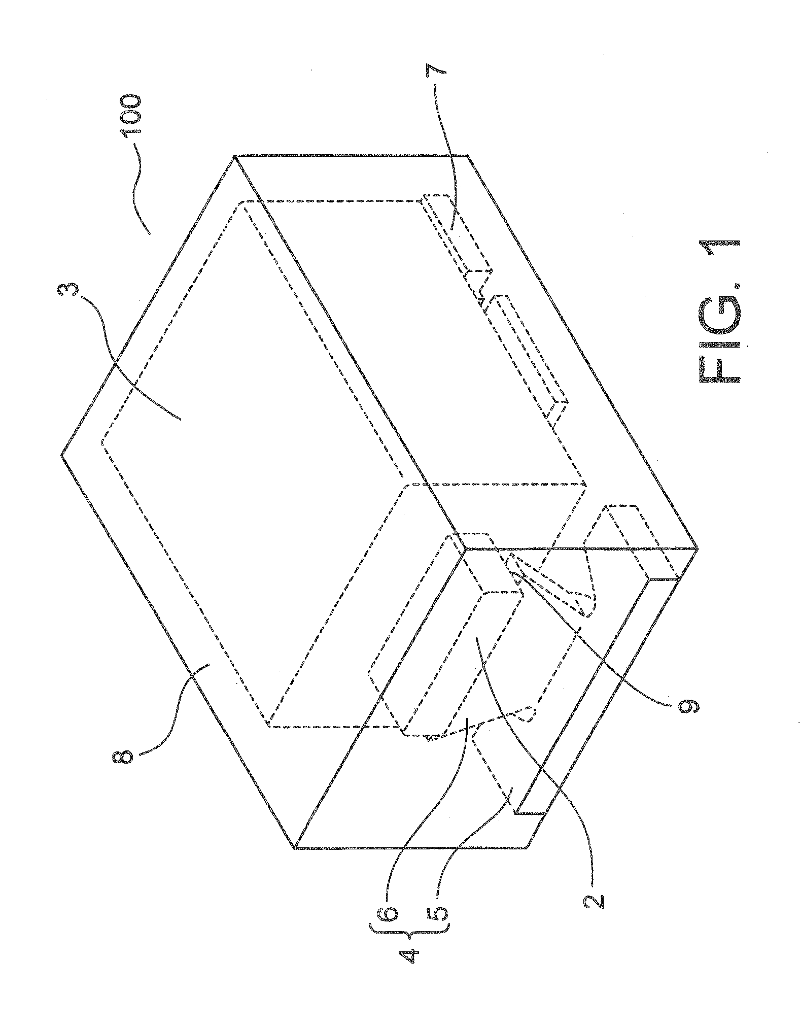
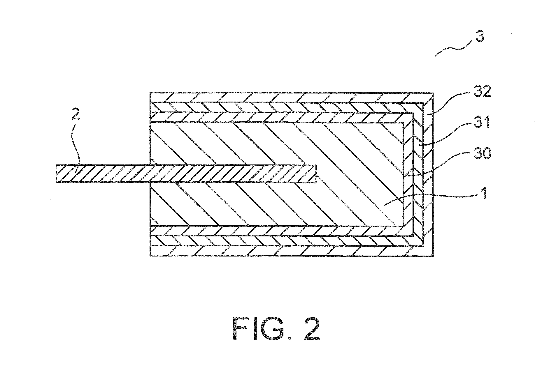
[0024]FIG. 1 is a perspective view for illustrating a solid electrolytic capacitor according to a first embodiment of this invention. The solid electrolytic capacitor according to the first embodiment of this invention is described with reference to FIGS. 1 and 2. As illustrated in FIG. 1, a solid electrolytic capacitor 100 of this embodiment includes a capacitor element 3, an anode terminal 4, a cathode terminal 7, and an exterior resin 8. In FIG. 2, the capacitor element 3 has an anode body 1, or a sintered compact 1 of valve action metal powder, which anode body or compact serves as an anode. The capacitor element 3 has a flat plate-like anode wire 2 delivered from the anode body 1.

[0025]Over a surface of the sintered compact 1 obtained by molding valve action metal powder and sintering the resultant at high temperature, there are formed sequentially a dielectric layer 30 including an oxide film and the like, an electrolyte layer 31 including a conductive polymer layer and the li...

second embodiment

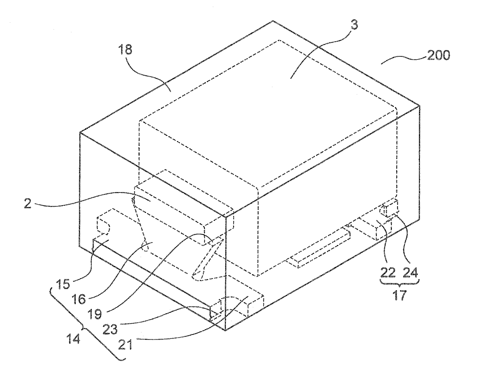
[0033]FIG. 3 is a perspective view for illustrating a solid electrolytic capacitor according to a second embodiment of this invention. The solid electrolytic capacitor according to the second embodiment of this invention is described with reference to FIG. 3. As illustrated in FIG. 3, a solid electrolytic capacitor 200 of this embodiment includes, a capacitor element 3, an anode terminal 14, a cathode terminal 17, and an exterior resin 18. As the capacitor element, the one as shown in FIG. 2 is used. That is, the capacitor element 3 has an anode body 1, or a sintered compact 1, of valve action metal powder, which anode body or compact serves as an anode. The capacitor element 3 has a flat plate-like anode wire 2 delivered from the anode body 1.

[0034]Over a surface of the sintered compact 1 obtained by molding valve action metal powder and sintering the resultant at high temperature, there are formed sequentially a dielectric layer 30 including an oxide film and the like, an electrol...

third embodiment

[0045]A solid electrolytic capacitor according to a third embodiment of this invention includes a capacitor element, an anode terminal, a cathode terminal, and an exterior resin. The capacitor element has an anode body, or a sintered compact of valve action metal powder, which anode body or compact serves as an anode. The capacitor element has a circular anode wire delivered from the anode body.

[0046]The anode terminal has a mounting portion and an upright portion that is raised from the mounting portion toward the anode wire of the capacitor element. In this case, the upright portion is connected to the mounting portion by welding. In other words, the anode terminal is formed by connecting the upright portion and the mounting portion to each other by welding, which are different members.

[0047]The upright portion has a main surface and side surfaces. The upright portion has a surface, opposed to the main surface, which has the same shape as the main surface. A length of an edge of t...


PUM

PropertyMeasurementUnit
widthaaaaaaaaaa
thicknessaaaaaaaaaa
lengthaaaaaaaaaa

Abstract

A solid electrolytic capacitor includes: a capacitor element including a sintered compact of a valve action metal, a dielectric layer, an electrolyte layer, and a cathode layer sequentially formed over a surface of the sintered compact, and an anode wire drawn out of the sintered compact; an anode terminal; a cathode terminal; and an exterior resin. The anode terminal includes a mounting portion and an upright portion. The upright portion has a trapezoidal shape. A length of a welding surface corresponding to an edge of the upright portion on the anode wire side is set to be longer than a length of the upright portion on the mounting portion side and to be longer than a width of the anode wire.

Description

[0001]This application is based upon and claims the benefit of priority from Japanese Patent Application No. 2014-198807, filed on Sep. 29, 2014, the disclosure of which is incorporated herein in its entirety by reference.BACKGROUND OF THE INVENTION[0002]1. Field of the Invention[0003]This invention relates to a solid electrolytic capacitor, and more particularly, to a solid electrolytic capacitor suitable for a chip-type solid electrolytic capacitor.[0004]2. Description of the Related Art[0005]As a chip-type solid electrolytic capacitor, there is generally known a configuration in which a capacitor element and part of an anode terminal and part of a cathode terminal are covered by an exterior resin. In such capacitors, exposed bottoms of an anode terminal and a cathode terminal serve as mounting surfaces for a board to be mounted.[0006]A configuration disclosed in Japanese Unexamined Patent Application Publication (JP-A) No. 2003-068576 (Patent Literature 1) is given as an example ...

Claims


Application Information

Patent Timeline
Patent Type & Authority Applications(United States)
IPC IPC(8): H01G9/15H01G9/012H01G9/08
CPCH01G9/15H01G9/08H01G9/012H01G9/10
Inventor KATO, JUNICHIMATSUSHIMA, YASUHIROTAKADA, DAISUKESAITO, KAZUAKI
Owner TOKIN CORP
Why Eureka
Try Eureka