
Chicane Blanker Assemblies for Charged Particle Beam Systems and Methods of Using the Same

a technology of charged particle beams and blankers, which is applied in the field of blanking charged particle beams, can solve the problems of plasma-focused ion beams, image saturation, and staining around samples, and achieve the effect of preventing neutrals

Active Publication Date: 2016-03-31
FEI CO
View PDF20 Cites 3 Cited by
  • Summary
  • Abstract
  • Description
  • Claims
  • Application Information

AI Technical Summary

Benefits of technology

The patent is about a method for protecting a sample from damage caused by neutrals (uncharged particles) when processing it using a charged particle system. The method involves using a charged particle source to emit charged particles, which are then focused into a beam that is directed towards the sample. A series of deflectors is used to deflect the beam around two structures that block neutrals, and the beam is then directed onto the sample surface. This prevents neutral particles from impacting the sample during processing. The technical effect of this method is to improve the accuracy and precision of charged particle processing, allowing for improved manufacturing of semiconductor devices.

Problems solved by technology

One issue encountered when using FIB systems, particularly P-FIB systems, is staining around areas of a sample irradiated with the plasma-focused ion beam.
Image saturation is another issue encountered when P-FIB devices are used in dual beam systems.
In some cases, particularly when the PFIB column has been configured to produce large ion currents, the neutral current may generate such a large background signal that “white-out” conditions are created, making SEM imaging is impossible.

Method used


Image

  • Chicane Blanker Assemblies for Charged Particle Beam Systems and Methods of Using the Same
  • Chicane Blanker Assemblies for Charged Particle Beam Systems and Methods of Using the Same
  • Chicane Blanker Assemblies for Charged Particle Beam Systems and Methods of Using the Same

Examples


first embodiment

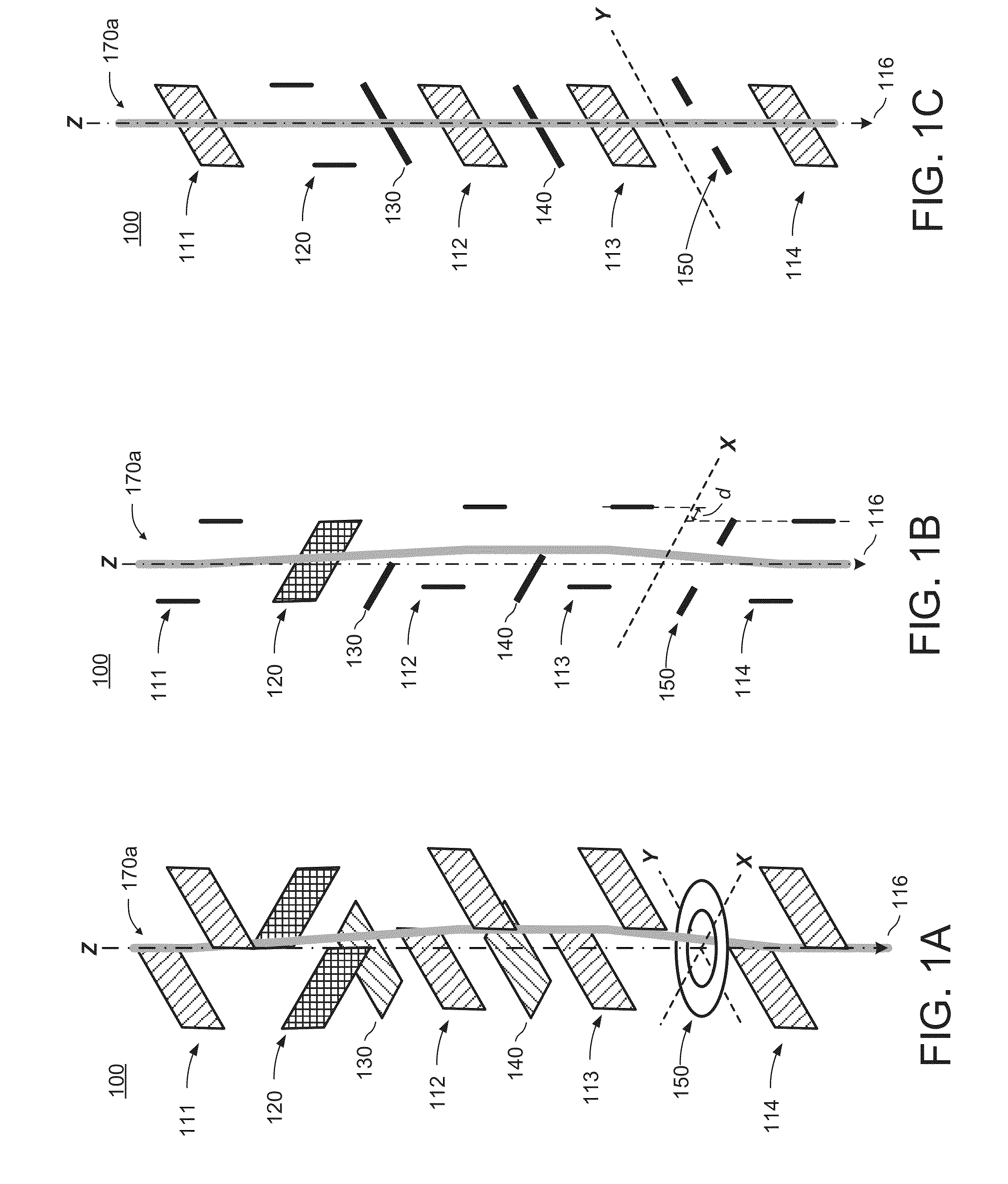
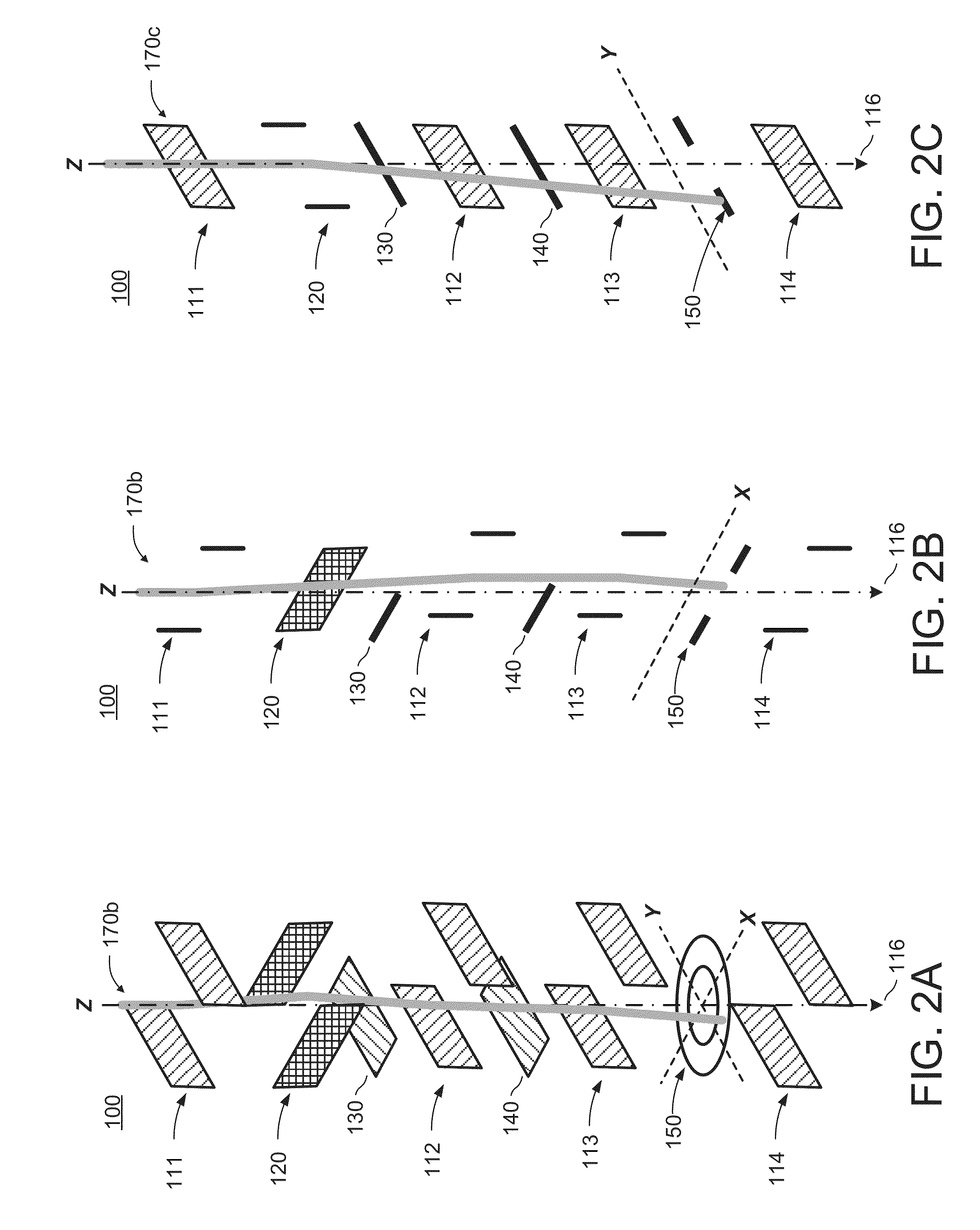
[0105]A first embodiment, which is a chicane blanker assembly for a charged particle beam system, comprising an entrance and an exit, wherein the entrance is configured to accept a beam of charged particles propagating along an axis; a neutrals blocking structure intersecting the axis; a plurality of chicane deflectors comprising a first chicane deflector, a second chicane deflector, a third chicane deflector, and a fourth chicane deflector sequentially arranged in series between the entrance and the exit and configured to deflect the beam along a path that bypasses the neutrals blocking structure and exits the chicane blanker assembly through the exit; and a beam blocking structure arranged between the third chicane deflector and the fourth chicane deflector.

[0106]A second embodiment, which is the chicane blanker assembly of the first embodiment further comprising a beam blanking deflector configured to prevent the beam from passing through the exit by deflecting the beam into the ...

second embodiment

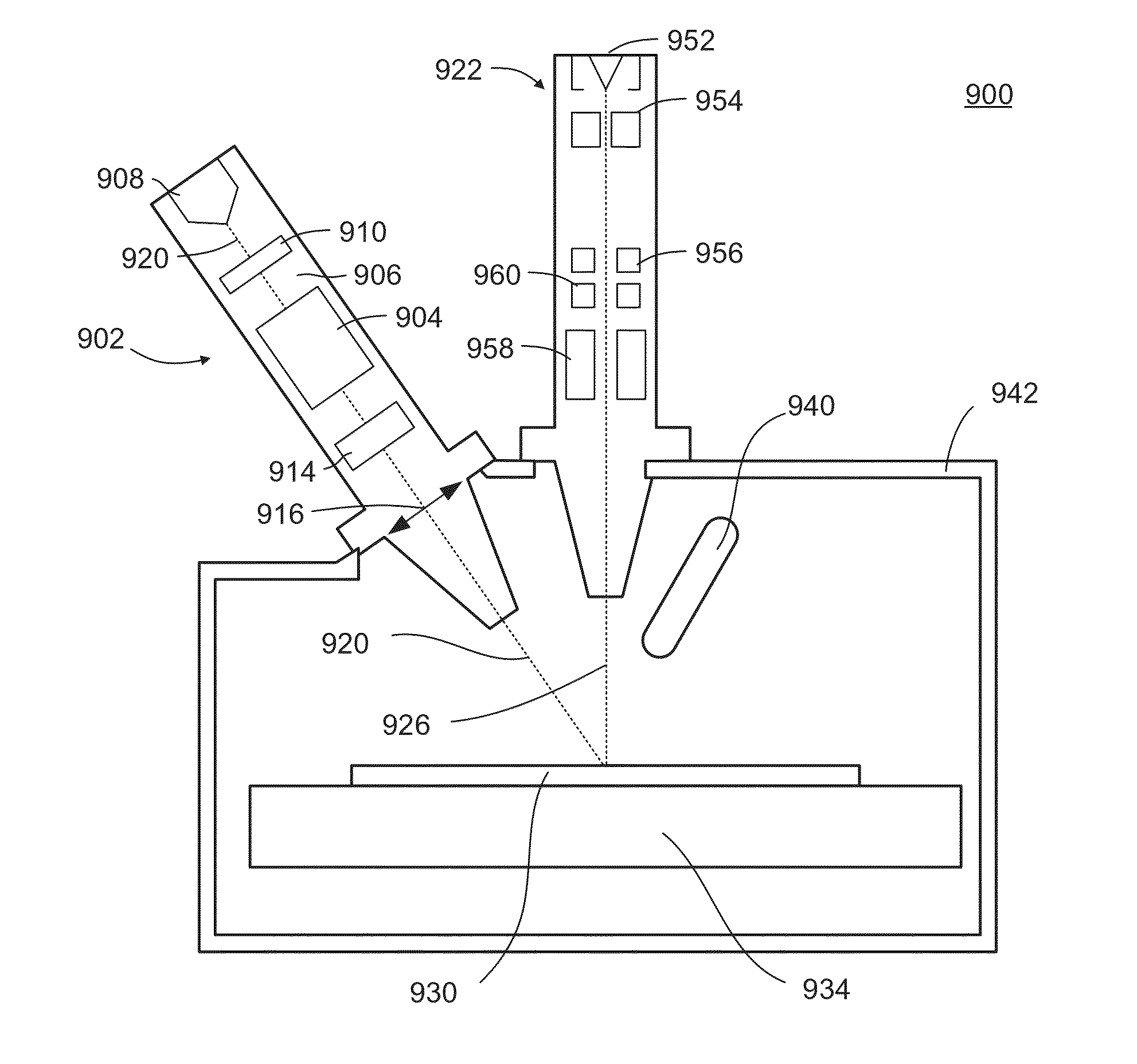
[0142]A twenty-second embodiment, which is a charged particle beam system for processing a workpiece, comprising a focused ion beam column configured to generate, focus, and direct an ion beam, wherein the focused ion beam column includes:

[0143]an ion source;

[0144]an optical axis for propagating the ion beam from the ion source towards a workpiece; and

[0145]a chicane blanker assembly comprising four chicane deflectors arranged in series, a blanking deflector, a first neutrals blocking structure, a second neutrals blocking structure, and a beam blocking structure, wherein:

[0146]the first neutrals blocking structure is configured to block neutrals propagating towards a workpiece along the optical axis;

[0147]the four chicane deflectors are configured to direct the beam onto the workpiece by deflecting the ion beam from the optical axis, onto a path bypassing the first neutrals blocking structure and the second neutrals blocking structure, and back onto the optical axis or an axis paral...


PUM


Abstract

A chicane blanker assembly for a charged particle beam system includes an entrance and an exit, at least one neutrals blocking structure, a plurality of chicane deflectors, a beam blanking deflector, and a beam blocking structure. The entrance is configured to accept a beam of charged particles propagating along an axis. The at least one neutrals blocking structure intersects the axis. The plurality of chicane deflectors includes a first chicane deflector, a second chicane deflector, a third chicane deflector, and a fourth chicane deflector sequentially arranged in series between the entrance and the exit and configured to deflect the beam along a path that bypasses the neutrals blocking structure and exits the chicane blanker assembly through the exit. In embodiments, the chicane blanker assembly includes a two neutrals blocking structures. In embodiments, the beam blocking structure is arranged between the third chicane deflector and the fourth chicane deflector.

Description

TECHNICAL FIELD[0001]The present invention relates to methods, apparatuses, and systems for blanking charged particle beams, such as plasma-focused ion beams.BACKGROUND[0002]Focused ion beam (FIB) systems are used in a variety of applications in integrated circuit manufacturing and nanotechnology to create and alter microscopic and nanoscopic structures. FIB systems can use a variety of sources to produce ions, such as a plasma source or a liquid metal ion source (LMIS), which are then focused onto a sample for imaging and milling. In recent years, various FIB systems utilizing a plasma source to generate a plasma focused ion beams (P-FIBs) have been developed. P-FIB systems are capable of producing higher current focused ion beams than may typically be achieved by FIB systems utilizing other ion sources, such as liquid metal ion sources. The higher current focused ion beams of PFIB systems allow faster milling rates to be achieved in sample-processing applications, which may be par...

Claims


Application Information

Patent Timeline
IPC IPC(8): H01J37/32
CPCH01J37/32009H01J2237/28H01J2237/32H01J2237/0042H01J37/045H01J37/05H01J2237/004H01J2237/028H01J2237/057H01J2237/15H01J2237/31745H01J2237/31749
Inventor KAGARICE, KEVINOTIS, CHARLESPARKER, N., WILLIAM
Owner FEI CO
Learn More