Microfluidic device for cell spheroid culture and analysis

a microfluidic device and cell spheroid technology, applied in the field of microfluidic devices, can solve the problems of spheroids of various sizes not being able to provide reliable information for drug testing, affecting the practical use of spheroid culture, and affecting the practicality of us

Inactive Publication Date: 2016-04-07
ACAD SINIC
View PDF2 Cites 31 Cited by
  • Summary
  • Abstract
  • Description
  • Claims
  • Application Information

AI Technical Summary

Benefits of technology

[0010]In one embodiment, the microfluidic device comprises: a main body; a fluid channel extending inside the main body and having two inlets and an outlet open to the outside; and a plurality of c...

Problems solved by technology

Traditional spheroid formation methods such as hanging drops, culture of cells on non-adherent surfaces, spinner flask, or NASA rotary cell culture system usually produce various sized spheroids, which is inconvenient for many biomedical applications (Friedrich et al.
For instance, spheroids with various sizes are unable to provide reliable information for drug testing due to the size dependent resistance of tumor spheroids.
Formation of cell spheroid culture devices posesses some drawbacks that retard their practical use.
The multilayer device with semi-transparent membranes suffers from the problem of high fidelity imaging and real time monitoring.
In addition, the spheroids cannot be easily harvested from the devices due to their channel designs without additional i...

Method used


Image

  • Microfluidic device for cell spheroid culture and analysis
  • Microfluidic device for cell spheroid culture and analysis
  • Microfluidic device for cell spheroid culture and analysis

Examples


first embodiment

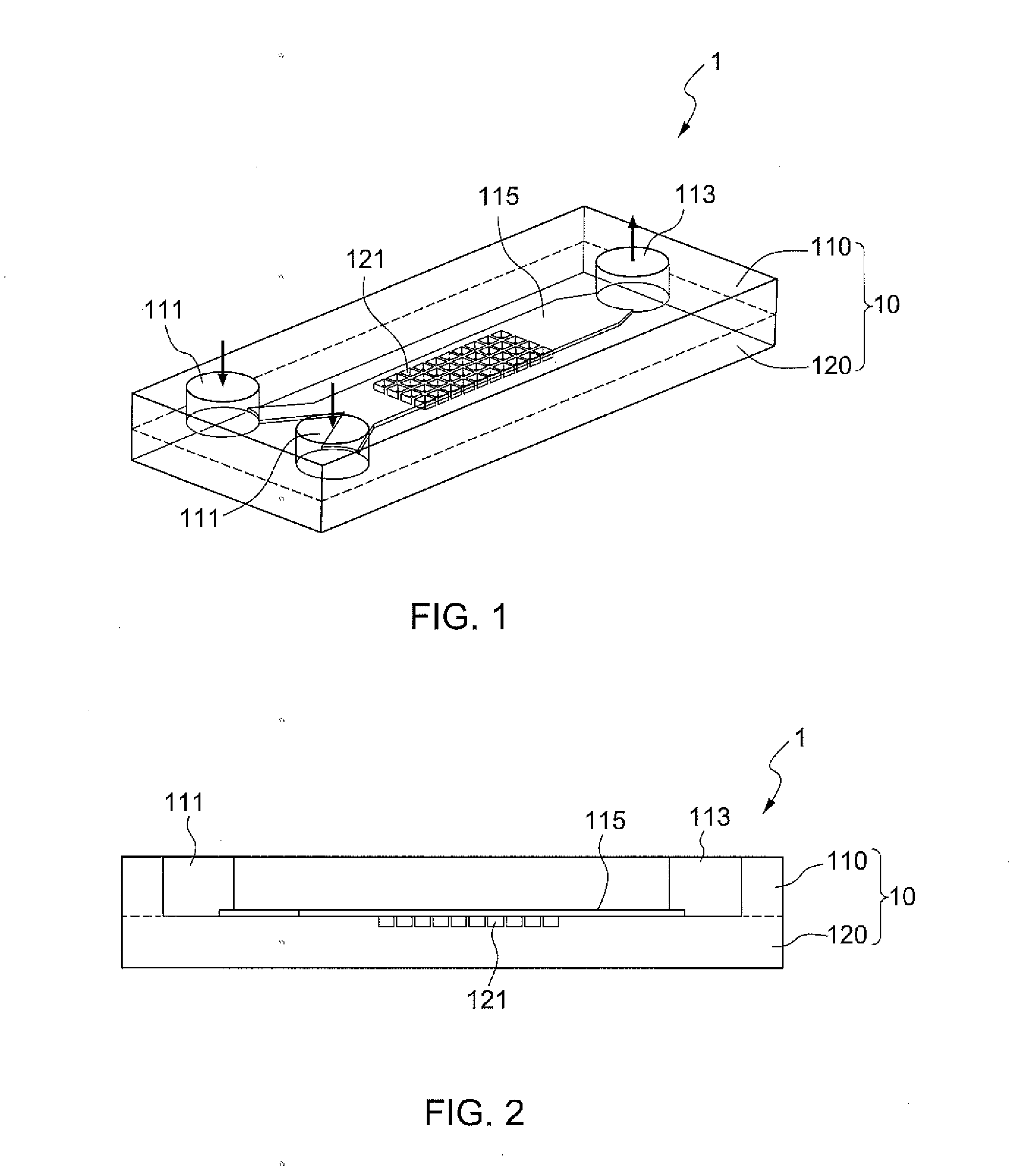
[0027]FIG. 1 illustrates a microfluidic device 1 according to the present disclosure, which is used for cell spheroid formation. The microfluidic device 1 substantially comprises a main body 10, a fluid channel 115 horizontally extending inside the main body 10; the fluid channel 115 has at least one inlet and outlet, and in this embodiment, it has two inlets 111 and an outlet 113, both of which are open to the outside. A plurality of chambers 121 for culturing cell spheroids are formed underneath and open to the fluid channel 115. The fluid channel 115 diverges into two smaller channels which communicate to the outside through each of the two inlets 111, respectively. In this embodiment, the two inlets 111 and the outlet 113 are open to the top surface of the main body 10. The chambers 121 are preferably arranged in a matrix array.

[0028]As shown in FIG. 2, the main body 10 is in a cuboid shape and preferably constructed using two polydimethylsiloxane (PDMS) layers: a top layer 110 ...

third embodiment

[0034]FIG. 5A illustrates a microfluidic device 3 according to the present disclosure. The microfluidic device 3 has a main body 30; a fluid channel 315 horizontally extends inside the main body 30 and has an inlet 311 and an outlet 313 both open to the outside; a plurality of chambers 321 for culturing cell spheroids are formed underneath and open to the fluid channel 315. The main body 10 is in a cuboid shape and is made of PDMS. The path of the fluid channel 315 is formed as one or several U-turns. In addition, the chambers 321 underneath the fluid channel 315 are preferrably arranged in one or several matrix arrays (see FIG. 5B). The U-turn arrangement of the path of the fluid channel 315 provides a rather large space underneath the channel 315 for forming chambers 321 for culturing cell spheroids; the flow rate of the culture medium 140 for flushing the cultured cell spheroids can be maintained relatively high because of the relatively small cross section of the flow path throu...

fourth embodiment

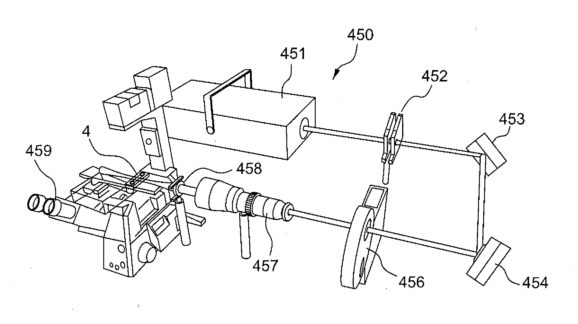
[0035]FIG. 6A illustrates a microfluidic device 4 according to the present disclosure, which is used for not only culturing cell spheroids but also for observing the cultured samples using the selective plane illumination microscopy (SPIM). SPIM is an optically sectioning microscopy technique for imaging large fluorescence samples. In SPIM, the sample is illuminated with a sheet of light that propagates perpendicularly to the direction of observation. Therefore, a fluorescence image of a finite depth, called a sectioned image, can be formed without lateral scanning. A stack of sectioned images acquired while the sample is moved along the direction of observation can be used to form a three dimensional (3D) view of a sample, such as a cellular spheroid. The spatial resolution of SPIM can be further improved by using proper image deconvolution methods, such that a single cell can be identified in a sample of a diameter larger than 100 μm. With these unique features, SPIM is especially...


PUM


Abstract

The invention relates to a microfluidic device for culturing spheroids of human or animal body cells. The device can generate ample numbers (e.g., 5000) of uniform-sized spheroids, and the spheroids can be harvested for conventional biochemistry analysis (e.g. flow cytometry). In addition, the device can be used for observing the cultured samples using selective plane illumination microscopy (SPIM). In at least one embodiment, the microfluidic device incorporates a main body; a fluid channel extending inside the main body and having two inlets and an outlet open to the outside; and a plurality of chambers for culturing cell spheroids which are formed at the underneath of the fluid channel.

Description

BACKGROUND OF THE INVENTION[0001]1. Field of the Invention[0002]The invention relates to a microfluidic device for culturing spheroids of human or animal body cells. The device can generate ample numbers (e.g. 5000) of uniform-sized spheroids, and the spheroids can be harvested for conventional biochemistry analysis (e.g. flow cytometry). In addition, the device can be used for observing the cultured samples using the selective plane illumination microscopy (SPIM).[0003]2. Description of the Related Art[0004]Microfluidic devices play more and more important roles for studies using spheroid cultures because of their capability of culturing cellular spheroids for several days. Recently, multi-cellular (three dimensional) tumor spheroid culture has played an important role in cancer research compared to the conventional dish-based, two-dimensional (2D) cell cultures. A multi-cellular spheroid establishes gradients in nutrients, metabolites, catabolites, and oxygen along the spheroid ra...

Claims


Application Information

Patent Timeline
IPC IPC(8): C12M1/00G01N33/483
CPCC12M23/58G01N33/4833C12M23/22C12M23/20C12M23/02B01L3/502761B01L2200/0694B01L2300/0816B01L2300/0864B01L2300/0883C12M23/12C12M23/16C12M29/10C12M41/36
Inventor TUNG, YI-CHUNGLEE, CHAU-HWANPATRA, BISHNUBRATA
Owner ACAD SINIC
Why Eureka
Try Eureka