Devices and methods to immobilize analytes of interest

a technology of immobilization and analytes, applied in the direction of chemical methods analysis, instruments, analysis using chemical indicators, etc., can solve the problems of unsatisfactory sample loss, target analyte loss, target analyte becoming trapped in filters, etc., to improve liquid sample processing, rapid and efficient immobilization of analytes, and high diffusion rate

Inactive Publication Date: 2005-11-17
HARVARD APPARATUS
View PDF46 Cites 58 Cited by
  • Summary
  • Abstract
  • Description
  • Claims
  • Application Information

AI Technical Summary

Benefits of technology

[0004] The invention provides improved liquid sample processing by separation and enrichment of target analytes from liquid samples due to rapid and efficient immobilization of the analytes to the binding materials on the surfaces of inserts inside pipette tips and / or housings. The size and shape of the insert can be controlled to produce a conformal annular gap between the surface of the insert and the inside wall of the housing. The conformal annular gap provides an open channel for the liquid sample to flow through at high diffusion rates that favor rapid analyte binding and minimal back pressure thereby allowing more rapid sample processing at higher enrichment ratios than can be achieved with currently available tip formats.

Problems solved by technology

Currently available methods for the separation and purification of analytes in micro-volumes by centrifugation or column methods often result in undesirable sample loss.
In current methods, target analyte losses often result from the target analyte becoming trapped in filters or other column components.
Liquid sample processing is difficult due to high resistance to fluid flow or undesirable increases in back pressure.
Since the material plugs the tip end through which the liquid sample is drawn, the flow of the liquid sample in both directions is impeded.
Consequently, when such tips are used in multi-tip configurations, variations in sample fluid flow may cause inconsistencies in the quantities of target analytes absorbed in different tips and the quality of the sample separation process.

Method used


Image

  • Devices and methods to immobilize analytes of interest
  • Devices and methods to immobilize analytes of interest
  • Devices and methods to immobilize analytes of interest

Examples


example 1

[0097] An array of multiple inserts will be prepared by dipping a three-dimensional polymeric body into a polymer coating solution. The polymer coating solution will be at a temperature slightly above the melting point of the polymer and the array of inserts will be dipped into the polymer coating solution for a period of time sufficient to coat the inserts. Thereafter, the array of inserts will be removed from the polymer coating solution and will be air dried.

[0098] Separately, a powder bath that will contain binding materials that can reversibly immobilize a analyte of interest will be prepared. For example, C1-8 alkyl ligands will be heat dried in a shallow dish at a temperature from about 80° C. to about 90° C. The array of inserts that have previously been coated with a polymer (e.g., polytetrafluoroethylene) will then be dipped / rolled in the powdered C18 alkyl ligands at a temperature where the polymer (e.g., polytetrafluoroethylene) softens so that the C18 alkyl ligands wil...

example 2

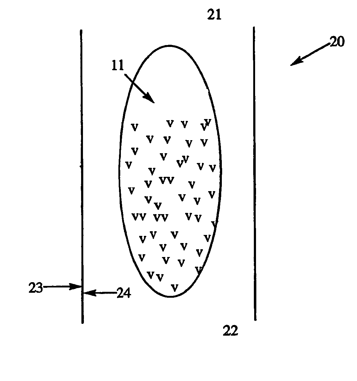
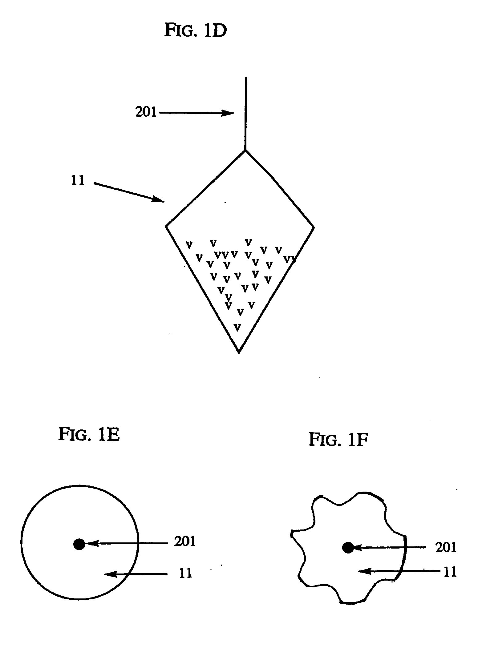
[0099] The method described in Example 1 will, in one embodiment, produce the insert array shown in FIG. 8. The insert array can have a primary connector 101 that holds the array of inserts 11, a handle 201 that connects each individual insert 11 to the primary connector 101, and binding materials v that cover at least a portion of the insert 11. The array of inserts will then be placed into housings (e.g., pipette tips) 20 as shown in FIG. 9. Thereafter, the connectors 201 will be cut so that the inserts 11 drop into the pipette tips 20. The pipette tips can then be released into a storage rack for packaging.

[0100] As shown in FIGS. 10A and 10B, the resulting pipette tip 20 will contain an insert 11, of which at least a portion is coated with binding materials v that will be capable of reversibly immobilizing a analyte of interest, and a cut secondary connector 201a. FIG. 10B, which is a top view of the pipette tip 20 shown in FIG. 10A shows that the insert 11 will not substantial...

example 3

[0102] This example demonstrates the use of insert arrays of the invention for producing analytes for analytical techniques, e.g., mass spectrometry, high performance liquid chromatography, electrophoresis and the like.

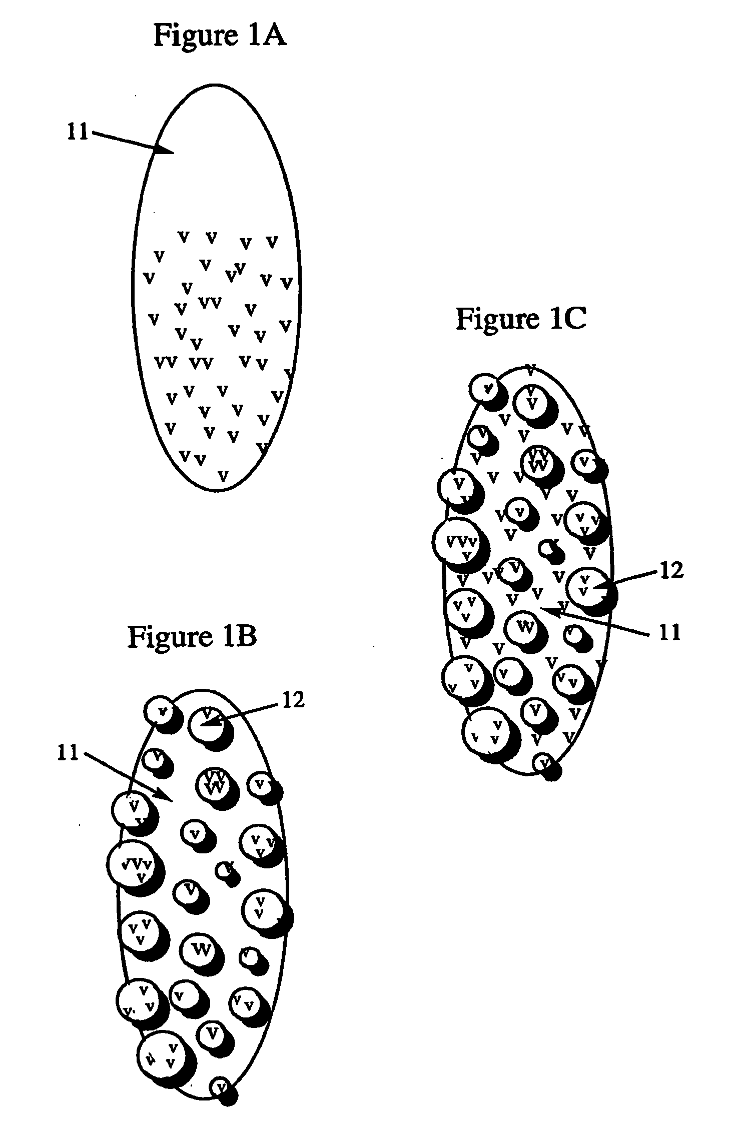
[0103]FIG. 11 shows an array 100 of inserts 11 of which at least a portion will be coated with binding materials v that will be capable of reversibly immobilizing an analyte of interest o. For example, the binding materials v can be chromatographic media, such as C18, and the analyte of interest o can be a peptide. Multiple inserts can be in the form of an array 100, where the array 100 is connected via structures 101 that will be manipulated for the experiment either automatically (e.g., through robotics) or manually. In alternative embodiments, the inserts can be within housings, such as those described herein and shown in FIGS. 9 and 10.

[0104] With reference to FIG. 11B, a housing 102 will hold a liquid sample 103 which will contain, inter alia, the analyte of in...


PUM

PropertyMeasurementUnit
volumeaaaaaaaaaa
particle sizeaaaaaaaaaa
pressureaaaaaaaaaa

Abstract

The invention provides devices and methods using assemblies of shaped inserts coated with diverse binder materials optionally positioned inside conformal housings. The devices are capable of immobilizing target analytes of interest (e.g., specific or groups of biomolecules) and are optionally usable as single units, linear strips or array formats. The coatings on the inserts and, optionally also on the inside walls of the housings, create variable gaps with narrow fluid paths resulting in enhanced diffusion and absorption of target analytes from transiting fluid samples while exhibiting minimal resistance to flow or back pressure commonly seen in conventional plug-type packings. The devices are intended for sample preparations requiring: filtering, enriching, separating, purifying of target analytes by selective absorption / elution as part of desalting, buffer exchange and / or enrichment applications in analyses by mass spectrometry and / or electrophoresis; purifying biomolecules; culturing cells; analytical separation processes, and general chemical, biological and / or biochemical separations in manual or automated systems.

Description

FIELD OF THE INVENTION [0001] The invention provides devices and methods that can immobilize analytes of interest in chemical, analytical, biochemical and / or biological applications. Immobilizing analytes of interest from liquid samples allows for filtering, separating, purifying, quantifying, characterizing, enriching, and / or identifying analytes of interest prior to analysis or identification of the analytes of interest by mass spectrometry, high performance liquid chromatography, electrophoresis, gas chromatography, UV spectrophotometry, and other analytical techniques. BACKGROUND OF THE INVENTION [0002] Currently available methods for the separation and purification of analytes in micro-volumes by centrifugation or column methods often result in undesirable sample loss. Since the amount and concentration of target analytes, such as proteins or bio-molecules, in a fluid sample is often low, the loss of even a small amount of the target analyte can represent a significant portion ...

Claims


Application Information

Patent Timeline
Patent Type & Authority Applications(United States)
IPC IPC(8): G01N1/34G01N21/00
CPCG01N1/405
Inventor SOSTEK, RONALDPERIANA, CECILYDAVIS, MARK
Owner HARVARD APPARATUS
Why Eureka
Try Eureka