Joined body and method for manufacturing the same

a technology of joining body and manufacturing method, which is applied in the field of joining body, can solve the problems of disadvantageous degradation of joining reliability, mechanical and electrical joining performance, etc., and achieve the effect of superior thermal history resistan

Active Publication Date: 2016-04-07
NGK INSULATORS LTD
View PDF0 Cites 7 Cited by
  • Summary
  • Abstract
  • Description
  • Claims
  • Application Information

AI Technical Summary

Benefits of technology

[0019]In the joined body and the method for manufacturing the same of the present invention, the first member and the second are joined to each other with the joint portion which at least partially includes the mixed layer containing metal of a transition metal and an oxide thereof. Since containing the oxide, this joint portion has a

Problems solved by technology

However, in the joined bodies disclosed in Patent Literatures 1 to 3, since a joint layer is formed of a metal, when a thermal history i

Method used


Image

  • Joined body and method for manufacturing the same
  • Joined body and method for manufacturing the same
  • Joined body and method for manufacturing the same

Examples


examples

[0053]Hereinafter, examples in each of which the joined body of the present invention was actually manufactured will be described as experimental examples. In addition, Experimental Examples 3 to 13 to the examples of the present invention, and Experimental Examples 1 and 2 correspond to comparative examples.

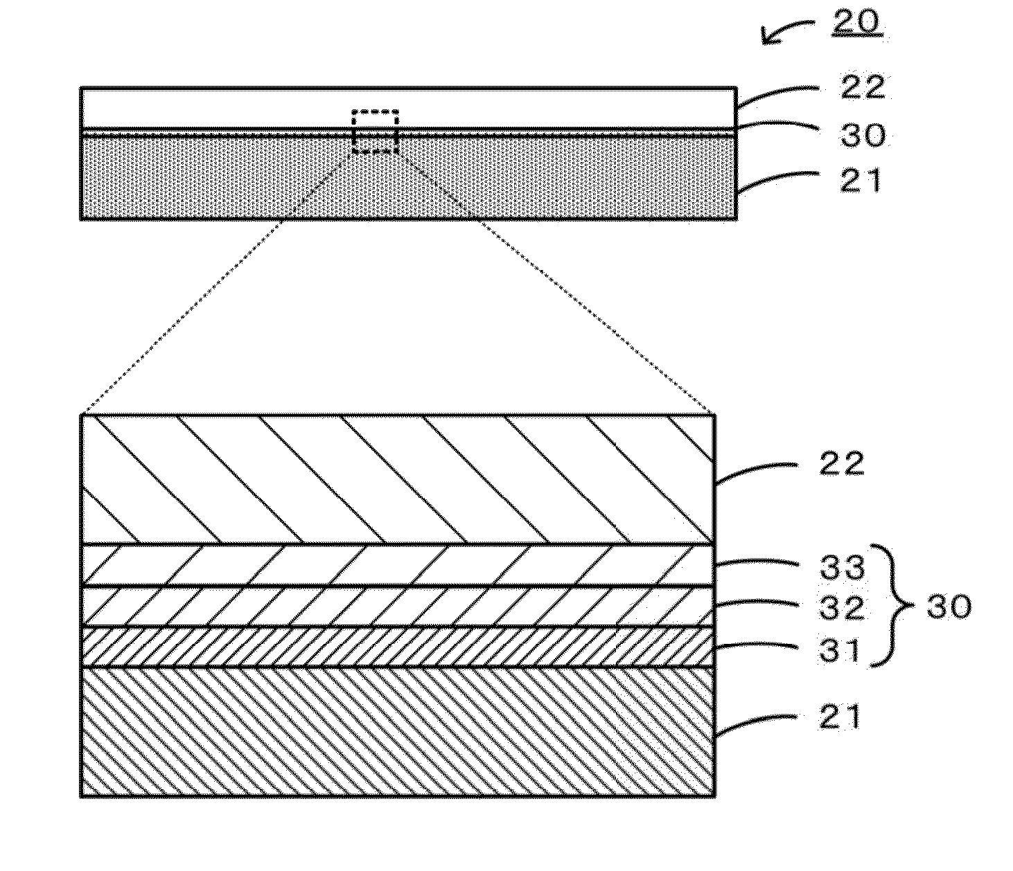
[0054][Formation Method]

[0055]First, Fe or Cu as a metal powder, a Ni oxide powder if needed as a solid solution component, a poly(vinyl butyral) resin (PVB) as a binder, and terpineol as a solvent were mixed together to form a joint material paste. This joint material paste was applied to a first member and a second member, each of which was an object to be joined, and those members were adhered to each other with the paste provided therebetween. A sample obtained by adhesion as described above was left in the air at 80° C. over one night, so that terpineol was sufficiently dried. A holding jig was placed on this sample so as to prevent the displacement of the two members and w...

experimental examples 1 to 13

[0061]In Experimental Examples 1 to 13, the formation was performed under the conditions shown in Table 1. As for a raw material of the joint portion, the addition amount of the oxide powder was set to 0 to 10 percent by mass with respect to the total of the metal powder and the oxide powder. In Experimental Examples 1 and 2, the joint portion had no mixed layer and was uniform, and in Experimental Examples 3 to 10, the thicknesses of the first layer, the second layer, and the mixed layer were changed. In Experimental Example 11, Cu was used for the joint portion. In Experimental Examples 12 and 13, the first member was changed. In addition, as for the coefficient of thermal expansion, SUS430 has 12 ppm / K, a Si-bonded SiC sintered body has 4.6 ppm / K, an Al2O3 porous body has 7.0 ppm / K, and LaCrO3 has 9.4 ppm / K.

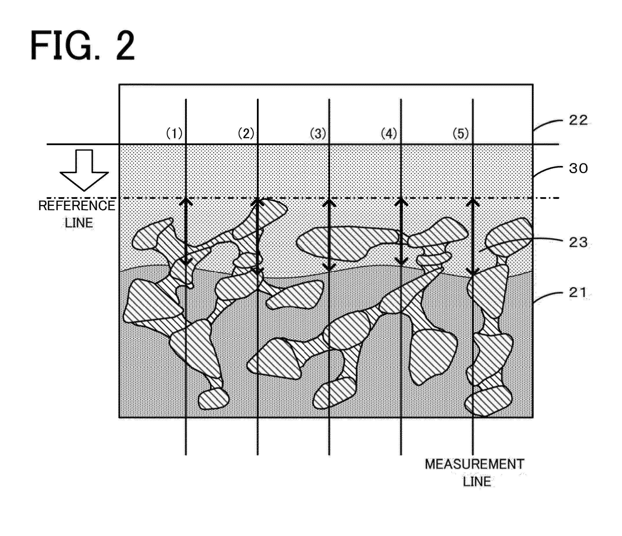
[0062](Observation of Joint Portion)

[0063]The joint portion of the joined body formed as described above was observed by a scanning electron microscope (SEM). As a result, it ...


PUM

PropertyMeasurementUnit
Temperatureaaaaaaaaaa
Fractionaaaaaaaaaa

Abstract

A joined body 20 includes comprises a first member 21, a second center 22 having a high coefficient of thermal expansion as compared to that of the first member 21, and a joint portion 30 which at least partially includes a mixed layer 33 containing metal of a transition metal and an oxide of the transition metal and which joins the first member 21 and the second member 22. In this joint portion 30, a first layer 31 containing a first oxide of a transition metal, a second layer 32 containing a second oxide of a transition metal having a low valence as compared to that of the first oxide, and the mixed layer 33 metal of a transition metal and an oxide thereof preferably are formed so as to form a multilayer structure.

Description

[0001]The present application claims priority from U.S. Provisional Application No. 62 / 059,219 filed on Oct. 3, 2014, the entire contents of which are incorporated herein by reference.BACKGROUND OF THE INVENTION[0002]1. Field of the Invention[0003]The present invention relates to a joined body and a method for manufacturing the same.[0004]2. Description of the Related Art[0005]Hitherto, as a joined body, a joined body in which a pair of electrodes each formed of a metal layer are provided on a. surface of a honeycomb body formed of a porous ceramic has been proposed (for example, see Patent Literature 1). According to this joined body, the metal layer contains Cr and / or Fe, a diffusion layer formed of a metal silicide is present at a boundary portion with the honeycomb body, and the reliability of the electrical joining is ensured in a high-temperature environment. In addition, as the joined body, a joined body has been proposed in which pores of a porous ceramic are filled with a c...

Claims


Application Information

Patent Timeline
IPC IPC(8): H01B5/00H01B1/04H01B13/00H01B1/08
CPCH01B5/002H01B13/0016H01B1/04H01B1/08C04B37/023C04B2237/123C04B2237/124C04B38/0019C04B2111/00793C04B35/565F01N3/027
Inventor IZUMI, YUNIEKOBAYASHI, YOSHIMASA
Owner NGK INSULATORS LTD
Why Eureka
Try Eureka