Ac-powered LED light engine

a led light engine and led light technology, applied in the direction of electroluminescent light sources, electric lighting sources, semiconductor lamp usage, etc., can solve the problems of only producing light, stroboscopic effects, epileptic seizures, etc., and achieve the effect of improving the power factor, number and cost of leds used in this embodimen

Active Publication Date: 2016-04-07
PHOTALUME INC
View PDF5 Cites 7 Cited by
  • Summary
  • Abstract
  • Description
  • Claims
  • Application Information

AI Technical Summary

Benefits of technology

[0012]The present invention provides an AC LED drive circuit which uses a minimal number of LEDs and provides both high efficiency power conversion and either continuous light output or minimal gaps between light outputs from successive power line half cycles, resulting in low flicker at 120 Hz, and a nearly sinusoidal power line current. One embodiment of the invention as described in detail below exhibits a power factor greater than 0.90.
[0016]Disclosed and claimed in a second embodiment is an arrangement using the same basic circuit as the first embodiment, but wherein solid state switches are incorporated so that substring B is shorted out when substring A has started conducting, and substring C is shorted out when substring D has started conducting. In this way, the resistively-limited conduction period is extended to overlap with the subsequent capacitively-limited operation. So-called “dead periods” are essentially eliminated in this embodiment and the current drawn from the power line is more nearly in phase with the power line voltage, improving the power factor while the total LED current remains relatively constant. The power factor of an AC circuit is typically defined as a ratio of actual power dissipated by the circuit to the product of its rms voltage and rms current. The power factor is generally used as a way to measure how efficiently the AC voltage line power is being used.
[0017]Disclosed and claimed in a third embodiment is a circuit in which two substrings of LEDs are connected to the power line by a capacitor at their common point. This capacitor drives these two substrings like a charge pump, first pulling charge out of the one substring and then pushing it into the other substring. A full bridge rectifier, connected to the power line, has its output joined to the two ends of the substrings through resistors. Therefore, at the peak of the power line voltage waveform, the resistively-limited current (galvanic current) passes through both substrings. In this manner, the LED current is continuous and the ripple current which is present is primarily at a frequency of 240 Hz or higher. The number and cost of the LEDs used in this embodiment may be reduced when compared to the first two embodiments, as a result of including a full bridge rectifier (i.e., only a “positive” substring pair is required for use with the rectified current).

Problems solved by technology

One weakness of such products was that the light was only produced at the peak of the AC power line, when the instantaneous power line voltage exceeded the sum of the forward voltages of the LEDs.
This short duration flash, repeated at 120 Hz, could cause stroboscopic effects and for some vulnerable persons might even induce epileptic seizures.
However successful these products have been, they have not found application in the most demanding applications—such as task lighting, workshop lighting and office lighting.
This lack of success is due, at least in part, to the fact that there is still a residual stroboscopic effect in these switch-controlled arrangements.
Although not noticeable by most people most of the time, this effect can produce headaches and eye strain if these light sources are used in these task, workshop and / or office light applications (among others).
However, defining flicker in this fashion may not relate well to the perception of the human eye when extremely rapid fluctuations are present.
In particular, if tiny notches of 2 msecs or less are taken out of an LED current waveform, the human eye cannot react fast enough to notice them.
However, the authors merely describe a parallel combination of a pair of bidirectional LED strings, the activation of one string of LEDs being resistively limited and the activation of the other, parallel string of LEDs being capacitively limited.
The Tan et al. paper does not provide a practical engineering solution as to how this could be done.
If the AC LEDs proposed by Tan et al. were replaced with LED strings enclosed by bridge rectifiers, fewer LEDs would be required, but the gap between light outputs from each half cycle becomes a major disadvantage.
U.S. Pat. No. 8,552,656 issued to Choi on Oct. 8, 2013 uses capacitors that are charged on positive half-cycles and negative half-cycles, respectively, to drive a single pair of LED arrays (which thus conduct alternately), and connects the LEDs directly to the ac power line with a series diode for each LED array, but is not capable of leveling the LED current.
As a result, a significant “flicker” remains.

Method used


Image

  • Ac-powered LED light engine
  • Ac-powered LED light engine
  • Ac-powered LED light engine

Examples


first embodiment

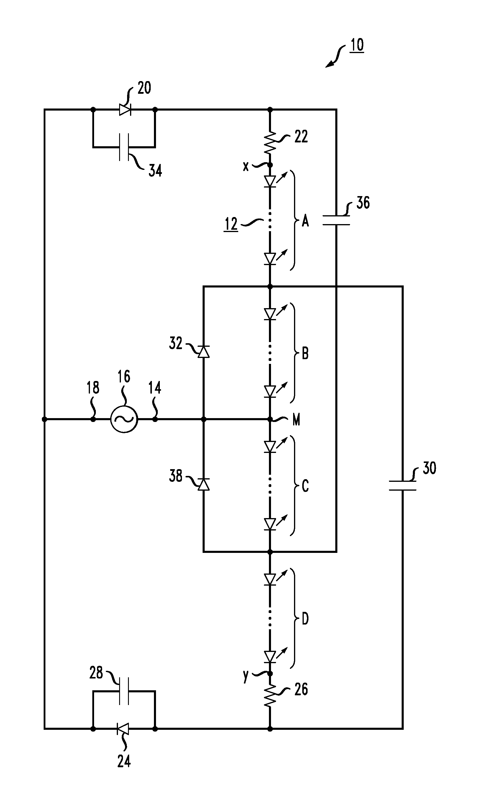
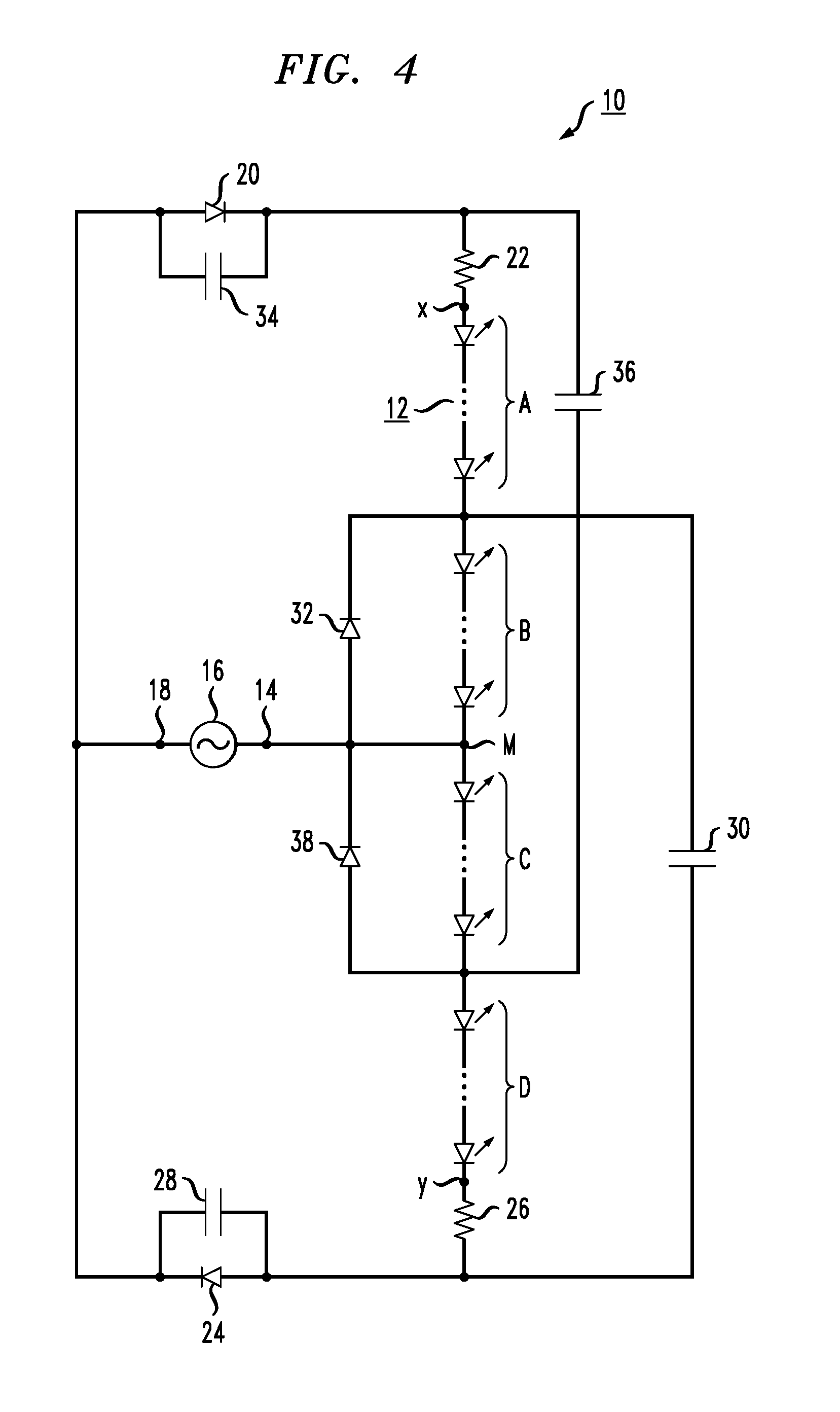
[0044]an AC-driven LED light engine 10 of the invention is depicted in FIG. 4. In this embodiment, a plurality of individual LEDs 12 are all connected in series in one continuous string. For purposes of operation, the string itself is subdivided into four substrings, shown as A, B, C and D in FIG. 4. Although it is convenient for manufacturing purposes for each substring to have the same number of individual LEDs, there may be some circumstances where it is advantageous to use different numbers of LEDs in each substring. In its most general form, LED light engine 10 can be configured to have any suitable number of separate LEDs within each substring.

[0045]Indeed, in this and all other embodiments the number of LEDs used in a substring will depend on the forward voltage of the specific LED devices being used, as well as the intended power line voltage (for US consumer applications, generally a 120V power line). By way of example only, the exemplary substrings of LEDs 12 as shown in F...

second embodiment

[0056]the invention is depicted in FIG. 8 as an LED light engine 40. Those components of LED engine 40 that provide the same functionality as LED engine 10 of FIG. 4 are shown by the same reference numeral. What is different in this particular embodiment is the inclusion of a pair of current-triggered switches that are placed across substrings B and C of LEDs 12 and are used to “short out” these substrings during the resistive-limited current portion of each half cycle. A first current-triggered switch 42 is disposed across substring B and is activated to bypass substring B by when the current through resistor 22 reaches its peak (positive) value. Similarly, a second current-triggered switch 44 is disposed across substring C and is activated to bypass substring C when the current through resistor 26 reaches its peak (negative) value. In this embodiment, therefore, substrings A and D are primarily used to supply LED current in the peak regions of the AC power line input, with substri...

third embodiment

[0062]the invention is shown as LED light engine 80 in FIG. 11. In this configuration, light engine 80 utilizes only a pair of LED substrings, denoted as substrings I and II in FIG. 11. At their midpoint M, a capacitor 82 is connected directly to a first terminal 84 of a power line connector 86. A pair of bias capacitors 88 and 90 is used to conduct displacement current directly back to an opposing terminal 92 of power line connector 86. These capacitors, together with capacitor 82, constitute the capacitive means responsible for producing the distinctive hump associated with displacement current in the output current waveform, as particularly shown in FIG. 12.

[0063]A set of diodes 94, 96, 98 and 100 comprises a full bridge rectifier arrangement that provides rectified power to the opposing ends of substrings I and II through resistors 102 and 104, respectively. In particular, resistors 102 and 104 constitute the resistive means for driving the LEDs. It is to be remembered, as menti...


PUM


Abstract

AC LED light engines powered directly from the AC power line contain circuitry of resistors, capacitors, diodes and transistors which enables an array of LEDs to efficiently produce light with a relatively low level of flicker as perceived by the human eye. The LEDs are driven by a current which is alternately capacitively limited and resistively-limited. Capacitively-limited pulses of current are combined with resistively-limited pulses of current so that the resulting output current ripple is at frequencies of 240 Hz or above which the human eye cannot perceive. The combination of resistively-limited current and capacitively-limited current results in a current drain from the power line which is generally sinusoidal and can have a power factor in excess of 0.90, and a flicker index below 0.2.

Description

CROSS-REFERENCE TO RELATED APPLICATIONS[0001]This application is a continuation-in-part of U.S. application Ser. No. 14 / 595,565, filed Jan. 13, 2015, which claims the benefit of the following U.S. Provisional Applications: Ser. Nos. 61 / 940,830 (filed Feb. 17, 2014), 62 / 034,540 (filed Aug. 7, 2014), 62 / 041,192 (filed Aug. 25, 2014), and 62 / 056,591 (filed Sep. 28, 2014), where all of these pending applications are herein incorporated by reference.BACKGROUND OF THE INVENTION[0002]1. Field of the Invention[0003]The invention relates in general to an alternating current (AC)-powered light emitting device (LED) arrangement, and more particularly to an AC-powered LED light engine that is capable of producing light output with relatively low flicker while providing the desired high light emitting efficiency and power factor criteria.[0004]2. Description of the Related Art[0005]So-called AC LED diode products have become popular because one relatively small, flat module can be joined directl...

Claims


Application Information

Patent Timeline
Patent Type & Authority Applications(United States)
IPC IPC(8): H05B33/08H05B44/00
CPCH05B33/0821H05B33/0809H05B33/083H05B45/40H05B45/395Y02B20/30H05B45/48Y02B20/40
Inventor SHACKLE, PETER W.
Owner PHOTALUME INC
Why Eureka
Try Eureka