Stabilization apparatuses and methods for medical procedures

Active Publication Date: 2016-04-14
CEDARS SINAI MEDICAL CENT
View PDF4 Cites 10 Cited by
  • Summary
  • Abstract
  • Description
  • Claims
  • Application Information

AI Technical Summary

Benefits of technology

[0006]In various embodiments, the invention teaches an apparatus that includes a securing arm that includes a first end, a second end, a long axis, and a short axis; a connecting arm that includes a first end, a second end, a long axis, and a short axis; a positioning arm that includes a first end, a second end, a long axis, and a short axis; and a guiding arm that includes a first end, a second end, a long axis, and a short axis; wherein (1) the first end of the connecting arm is attached to the second end of the securing arm, (2) the second end of the connecting arm is attached to the first end of the positioning arm, (3) the long axis of the connecting arm is perpendicular to the long axis of each of the securing arm and positioning arm, (4) the first end of the securing arm and the second end of the positioning arm can be positioned to extend in substantially the same direction away from the connecting arm, (5) the positioning arm is attached at its second end to the second end of the guiding arm, such that the positioning arm and guiding arm are perpendicular to one another, and (6) the guiding arm can be positioned such that the axis along which its long axis is situated is perpendicular to but does not intersect with the axes along which the long axis of the securing arm and the long axis of the connecting arm are respectively situated. In some embodiments, the securing arm further includes one or more clamps on its first end, and the one or more clamps are configured to attach to an arm of a tissue retractor. In some embodiments, the guiding arm further includes an instrument attaching component configured to slide along the long axis of the guiding arm. In some embodiments, the instrument attaching component includes one or more clamps configured to clamp a medical instrument. In certain embodiments, the sli

Problems solved by technology

More specifically, certain medical procedures performed by physicians are associated with especially high risks of accidental patient injury and/or treatment failure, due to a combination of the nature of the tissues involved in the procedure, the high degree of accuracy demanded by the procedure, limitations of existing surgical instruments (including stabilizing apparatuses), limitations associated with the field of view, and human error.
Unfortunately, these devices are all either difficult to use (requiring a large amount of physician training), have an excessive part count (thereby carrying a

Method used


Image

  • Stabilization apparatuses and methods for medical procedures
  • Stabilization apparatuses and methods for medical procedures
  • Stabilization apparatuses and methods for medical procedures

Examples


example 1

Stereotactic Apparatus with Side Clamp

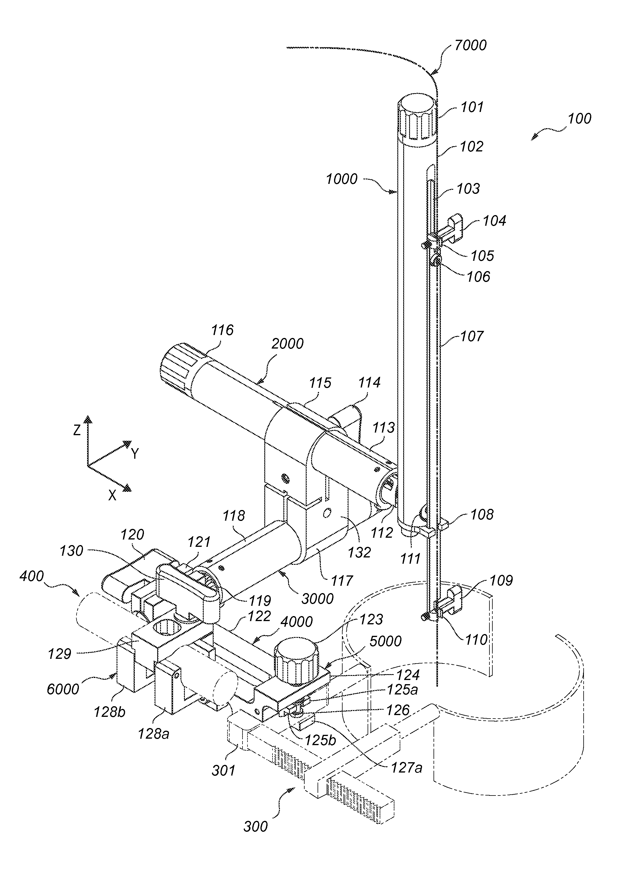
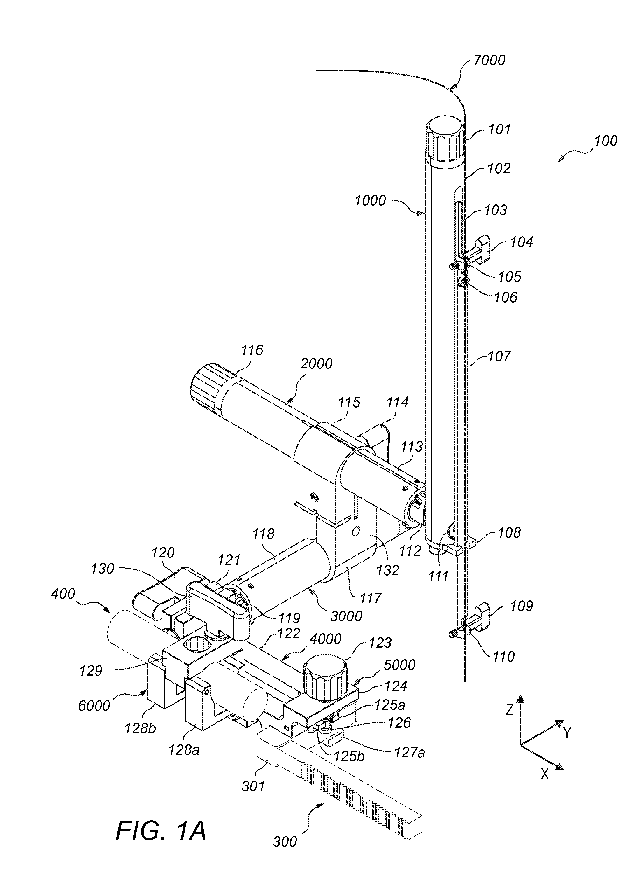
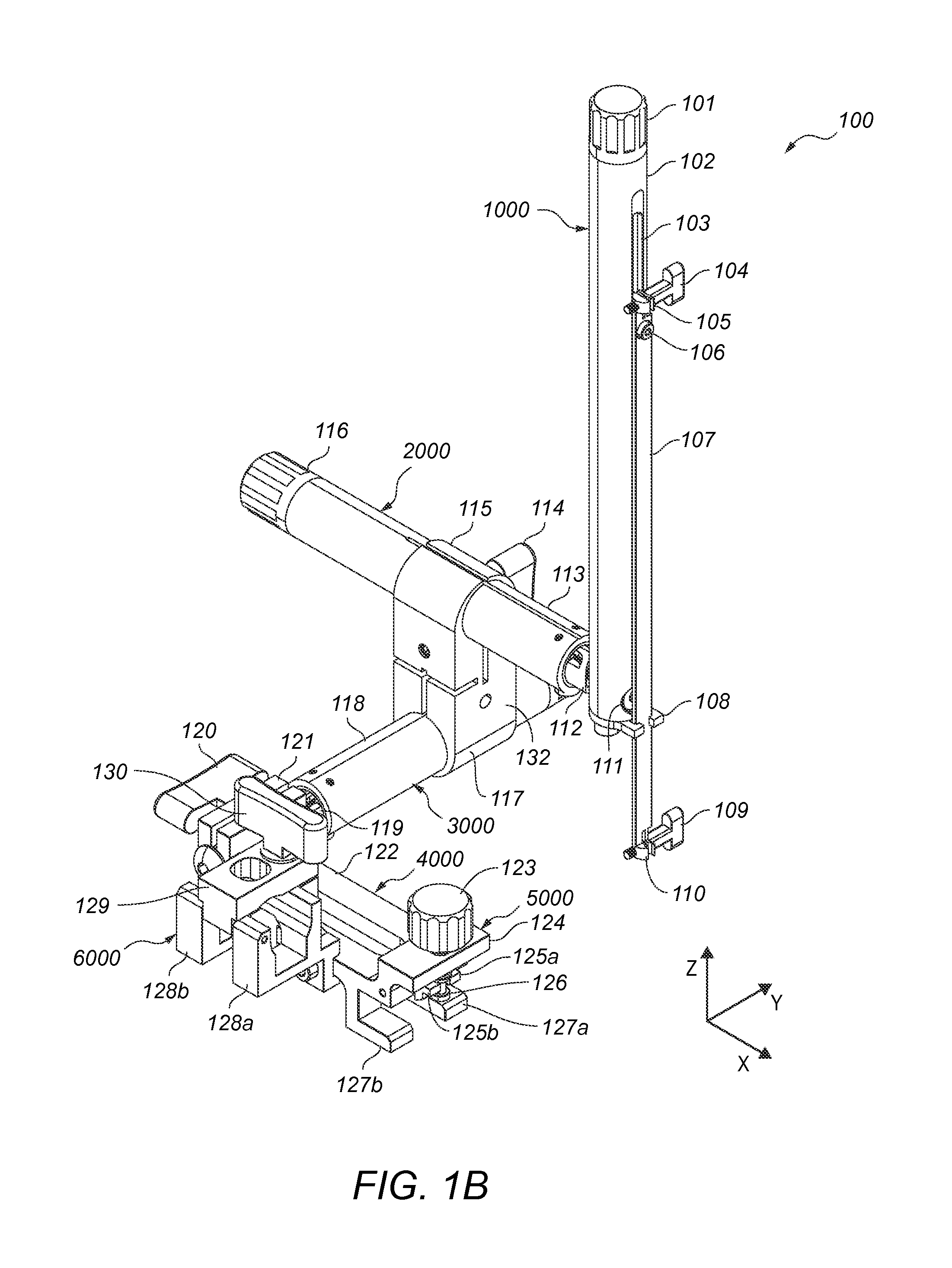
[0067]FIG. 1A depicts exemplary stereotactic apparatus 100. Stereotactic apparatus 100 includes guiding arm 1000, which includes an elongated channel 103 situated along its long axis (FIG. 1A). Guiding arm 1000 includes a dial 101 and an elongated cylindrical body 102 (FIG. 1A). Guiding arm 1000 also includes instrument attachment component 107, and clamps 105 and 110 which are tightened and loosened by screws 104 and 109, respectively (FIG. 1A). The guiding arm 1000 further includes instrument attachment component guide 108. FIG. 18 depicts an exploded view of guiding arm 1000, in which the assembly of threaded shaft 148, bushing 147, curved spring washer 146, radial ring 145, set screw 144, and dial 101 is shown. FIG. 18 also depicts the assembly of screws 153a and 153b, instrument attachment component guide 108 (with screw receiving holes 152a and 152b), cylindrical receiving stopper 151, and screw 133. FIG. 18 shows instrument attachment com...

example 2

Stereotactic Apparatus without Side Clamp

[0073]FIGS. 1C and 2C depict stereotactic apparatus 200, which includes the same components as stereotactic apparatus 100, with the exception of the side clamp 128 depicted in stereotactic apparatus 100. Stereotactic apparatus 200 also functions in the same way as stereotactic apparatus 100. with the exception of the functions that relate to side clamp 128.

example 3

Surgical Procedure

[0074]A single level laminectomy can be performed on the L4 vertebral segment. Standard anesthetic / preoperatory techniques are used and the patient is positioned prone. A 4 cm incision is made at the midline above the L4 spinous process. Cutting electrocautery is used to cut the fascia and extend the incision to the spinous process, as well as achieving hemostasis of any small hemorrhages from the incision site. At this point a Weitlaner retractor can be used to keep the incision open. A bilateral sub-periosteal dissection is performed carefully by elevating the muscles and periosteum off of the lamina. Cutting electrocautery is used to facilitate the dissection. The spinous process is then removed using a Leksell rongeur. A high-speed drill is used to thin the lamina laterally. The lamina is then lifted and the ligamentous attachment is cut to release the lamina. Kerrison rongeurs are then be used to extend the laminectomy or clean up any left over bone fragments....


PUM


Abstract

The present invention teaches minimally invasive apparatuses and methods for stabilizing and/or guiding medical instruments used in a variety of medical procedures, including (a) introducing one or more substances into a subject's body, (b) removing one or more substances from a subject's body, (c) manipulating a region of a subject's body, or (d) combinations thereof. Among the many advantages of the inventive apparatuses are their simplicity and adaptability to attach to a variety of retractors.

Description

CROSS-REFERENCE TO RELATED APPLICATION[0001]This non-provisional application claims the priority benefit of U.S. Provisional Patent Application No. 61 / 817,785, filed on Apr. 30, 2013, which is incorporated herein by reference in its entirety.FIELD OF THE INVENTION[0002]The present invention generally relates to apparatuses for medical procedures, and methods of use thereof.BACKGROUND[0003]All publications herein are incorporated by reference to the same extent as if each individual publication or patent application was specifically and individually indicated to be incorporated by reference. The following description includes information that may be useful in understanding the present invention. It is not an admission that any of the information provided herein is prior art or relevant to the presently claimed invention, or that any publication specifically or implicitly referenced is prior art.[0004]When physicians are performing procedures on or around certain areas of the body suc...

Claims


Application Information

Patent Timeline
IPC IPC(8): A61B18/20
CPCA61B19/201A61B18/20A61B2019/462A61B2019/268A61B2010/045A61B2562/0271A61B2218/005A61B2562/0233A61B2018/00595A61B2017/0262A61B2019/5236A61B2019/524A61B2019/5276A61B2562/0209A61B17/0206A61B90/50A61B90/11A61B2090/062A61B2017/3405A61B2090/571A61B2090/374A61B2090/3762A61B2090/378
Inventor AVALOS, PABLODRAZIN, DONIELSVENDSEN, CLIVE
Owner CEDARS SINAI MEDICAL CENT
Why Eureka
Try Eureka