Coil apparatus and method for inductive power transmission

Active Publication Date: 2016-04-21
ROBERT BOSCH GMBH
10 Cites 4 Cited by

AI-Extracted Technical Summary

Problems solved by technology

When traveling over curbs or poor-quality stretches of road, however, it is routinely expected in the case of road vehicles of conventional design that the underbody will contact or scrape along the curb/road surface.
Such contact leads to damage at the lowest part...

Benefits of technology

[0012]In accordance with a preferred development the coil apparatus also comprises an external pressure sensor, which senses an external pressure of the atmosphere. Here, the signal unit comprises a threshold value determination unit, which determines the internal pressure threshold value depending on the external pressure. This makes it possible to avoid false signals as a result of fluctuations of the atmospheric pressure and thus makes it possible to achieve a particularly high level of safety, without the need for an internal pressure deviating excessively from atmospheric pressure and for corresponding structural outlay, such as an excessive thickness of the housing wall.
[0013]In accordance with a preferred development the housing wall comprises an inner wall and an outer wall, which cover the coil on the transmission side. This means that the housing wall is designed on the transmission side in a double-walled manner. This on the one hand makes it possible to configure the coil apparatus with a very low volume of the housing medium, which is advantageous in terms of material costs and the overall weight of the coil apparatus, depend...

Abstract

The invention provides a coil apparatus (100) for inductive power transmission, comprising an electromagnetic coil (102) for emitting and/or picking up an electromagnetic field (112) on a transmission side (106) of the coil apparatus (100), and comprising a housing wall (104), which covers the coil (102) on the transmission side (106) and is transmissive to the electromagnetic field (112). Furthermore, the coil apparatus (100) comprises a housing medium (108), which is enclosed by the housing wall (104) in such a way that, when a through-opening (110) is formed in the housing wall (104), the housing medium (108) passes through the through-opening (110). Alternatively, a housing vacuum is provided which is enclosed by the housing wall in such a way that, when a through-opening is formed in the housing wall, atmospheric air (118) passes through the through-opening. Among further aspects, a vehicle comprising such a coil apparatus and a method for inductive power transmission are provided. The method comprises steps of providing an electromagnetic coil (102) for emitting and/or picking up an electromagnetic field (112), covering the coil (102) on a transmission side (106) with a housing wall (104) which is transmissive to the electromagnetic field (112), enclosing a fluid (116) with an internal pressure which is different than the atmospheric air by the housing wall (104),

Application Domain

Batteries circuit arrangementsCharging stations +8

Technology Topic

Electric power transmissionEngineering +6

Image

  • Coil apparatus and method for inductive power transmission
  • Coil apparatus and method for inductive power transmission
  • Coil apparatus and method for inductive power transmission

Examples

  • Experimental program(1)

Example

[0020]Unless expressly mentioned otherwise, like reference signs in the figures refer to like or equivalent elements.
DETAILED DESCRIPTION
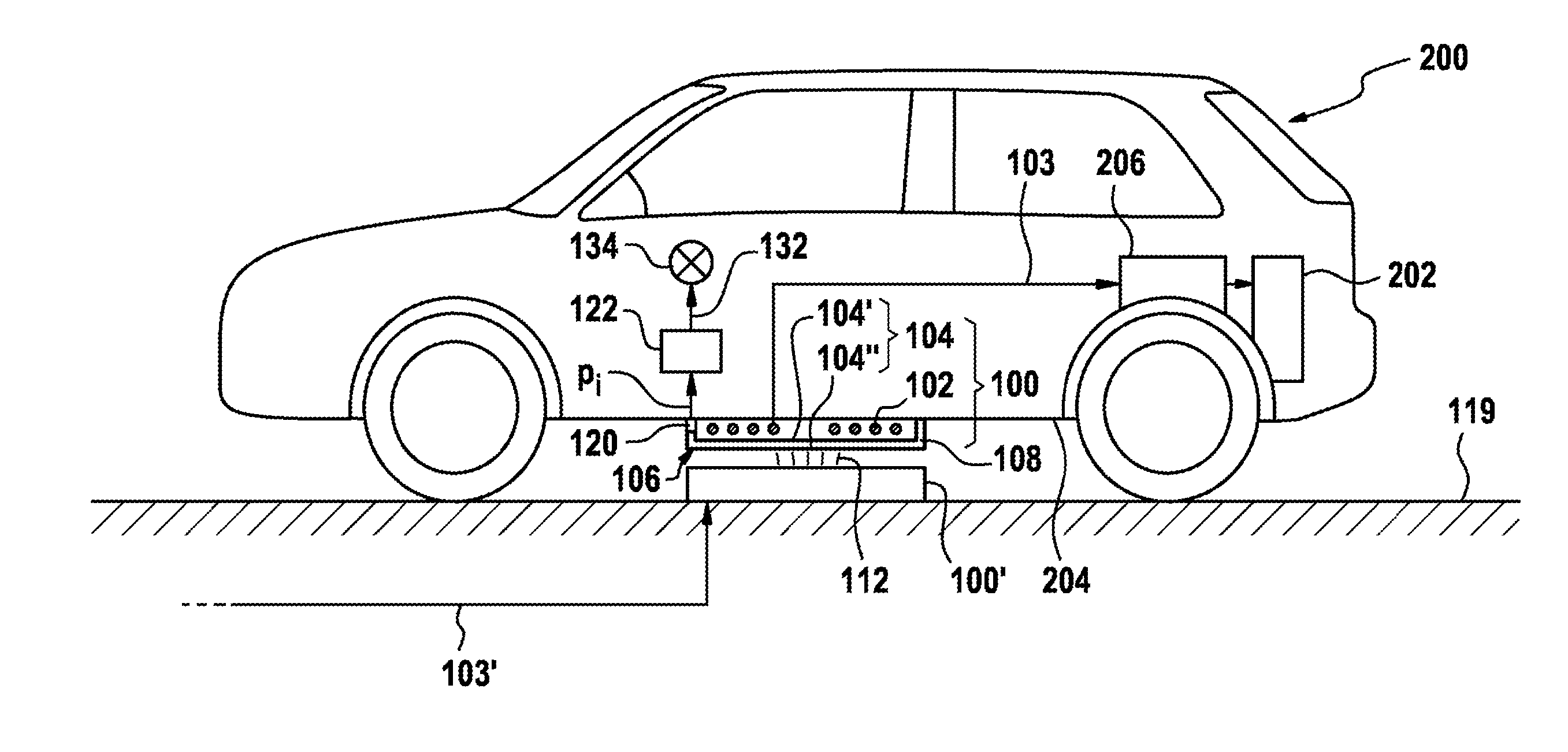
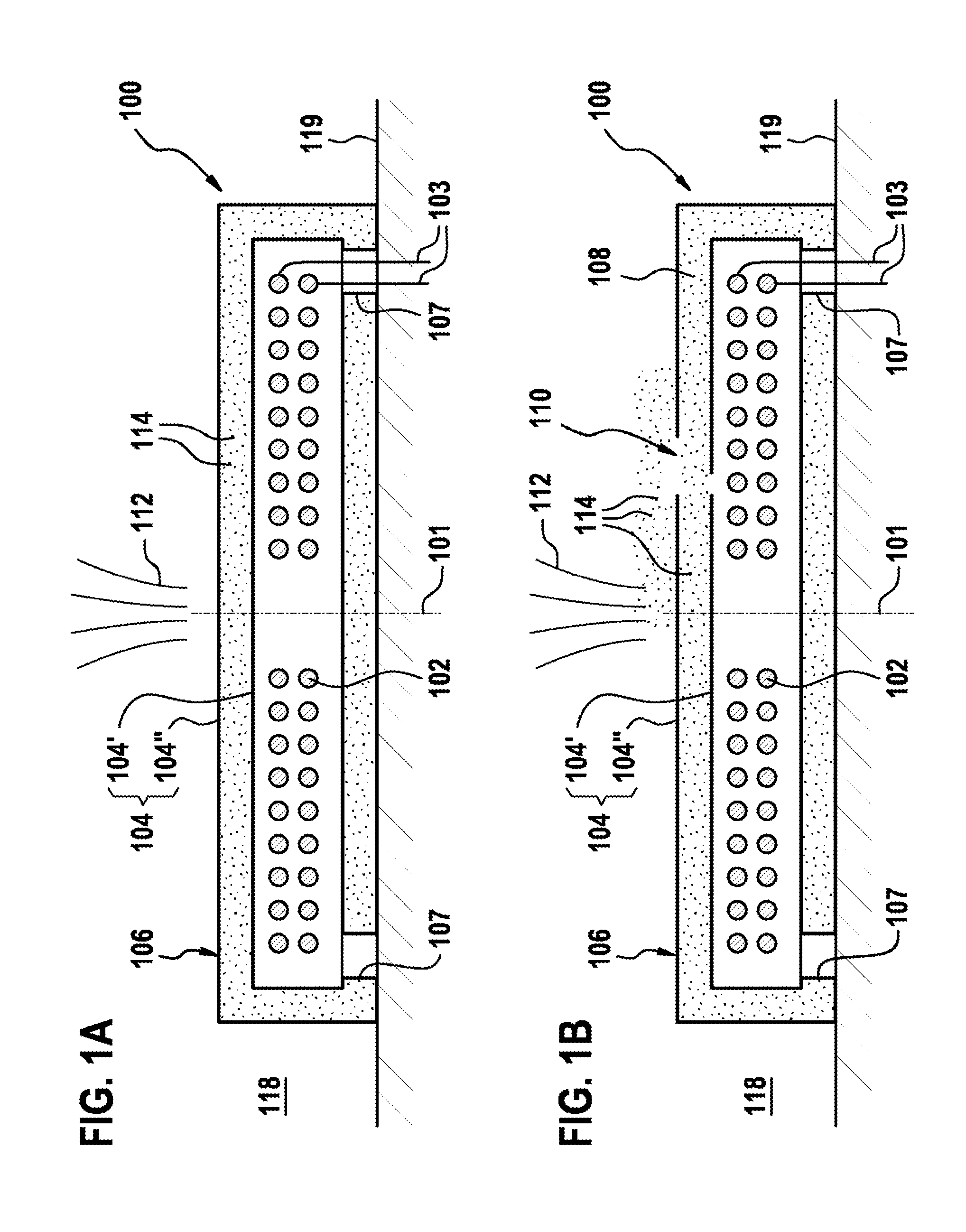
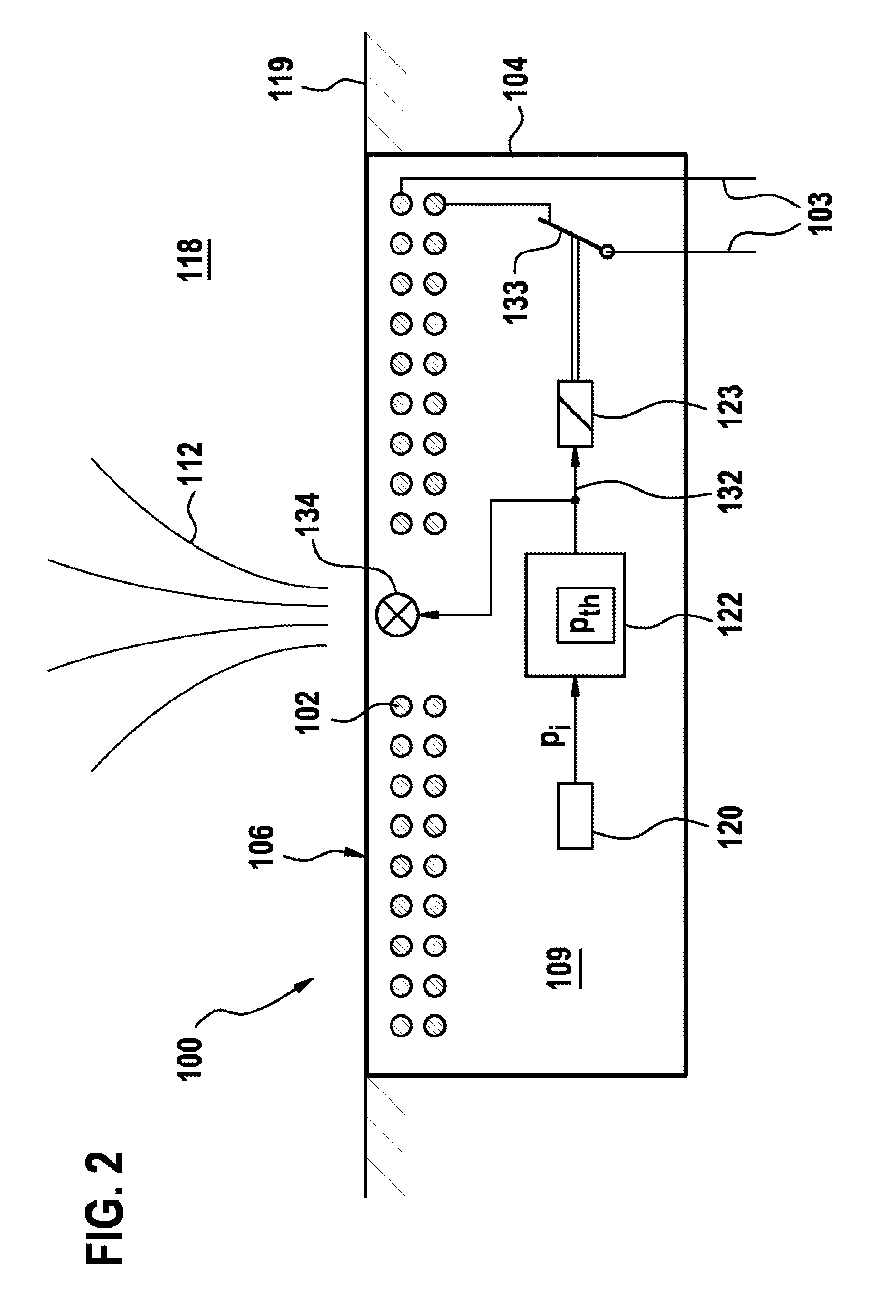
[0021]FIG. 1A, in a schematic cross-sectional view, shows a coil apparatus 100, arranged on the ground 119, for inductive power transmission by means of an electromagnetic field 112 to a further coil apparatus (not shown), which can be arranged above the upper side of the coil apparatus 100, designated as the transmission side 106, and for example can be mounted on an electric vehicle (not shown), which is to stop above the coil apparatus 100. The coil apparatus 100 comprises a coil 102, of which the windings are wound on the whole in the form of a flat cylinder, of which the axis of symmetry 101 lies in the drawing plane, and also a housing, which surrounds the coil 102 and likewise has a cylindrical wall 104.
[0022]The wall 104 of the housing of the coil apparatus 100 is double-walled peripherally with an inner wall 104′ and an outer wall 104″ made of an electrically non-conductive material, wherein, in order to support the inner wall 104′ on the underside of the coil apparatus facing away from the transmission side, spacers 107 are inserted between the inner wall 104′ and an outer wall 104″. A two-core feed line 103 for feeding electrical power into the coil 102 is guided outwardly through one of the spacers 107. The space located within the inner wall 104′, in which space the coil 102 is located, is filled with a suitable medium, for example an oil, a protective gas, or with air, which for example can be connected via the spacers 107 to the external air of the atmosphere 118 or can be sealed off with respect thereto.
[0023]The space located between the inner wall 104′ and outer wall 104″ of the housing is hermetically sealed with respect to the atmosphere 118 and is filled by a housing medium 108, which, besides air at low atmospheric pressure, also contains a dye in the form of a colored powder 114 of any color. The colored powder 114 is selected such that, if released in the event of damage to the outer wall 104″, it quickly spreads over a radius of a number of cm or dm and leaves behind easily noticeable traces. In alternative embodiments the housing medium may be enclosed at overpressure between the inner wall 104′ and the outer wall 104″.
[0024]FIG. 1B shows the coil apparatus from FIG. 1 in a damaged state following influence of mechanical force from above, i.e. from the transmission side 106. Due to the force influence, a small through-opening 110 has formed in the housing wall 104 and extends through an opening in the outer wall 104″ and a slightly smaller opening in the inner wall 104′ as far as the space located within the inner wall 104′, such that the coil 102 located therein is exposed in part. Due to the vibration during the force influence, the housing medium 108 located between the outer wall 104″ and inner wall 104′ has passed through the through-opening 110 into the atmosphere 118 outside the outer wall 104″ and has distributed the colored powder 114 contained in the housing medium 108 at the outer side of the outer wall 104″ in a radius of a number of centimeters. In the case of embodiments in which the housing medium is at overpressure with respect to the atmosphere 118, the overpressure assists the outward passage of the housing medium 108 and therefore the distribution of the colored powder 114. Due to its arbitrary color, the colored powder 114 is easily noticeable as a colored stain to the user of the coil apparatus 100, which allows the user to protect themself against the threat of an electric accident by switching off the electrical power feed via the feed line 103, and allows the user to repair or replace the coil apparatus 100.
[0025]FIG. 2 shows a coil apparatus 100 in accordance with a further embodiment, said coil device being arranged fully recessed in the ground 119, such that the housing wall 104 on the transmission side 106 terminates flush with the surface of the ground 119. In contrast to the embodiment from FIGS. 1A-B, the housing wall 104 is formed as a single wall, which hermetically surrounds an interior, in which the coil 102 is arranged. A housing vacuum 109 prevails in the interior enclosed by the housing wall 104, wherein the term “housing vacuum” is not limited to an ideal vacuum, but generally designates a situation in which the interior is filled with air or another gas or gas mixture having an internal pressure pi that is reduced compared with the atmosphere 118. In the present embodiment the internal pressure pi is 100 hPa by way of example. The feed line 103 is guided through the housing wall 104 in a hermetically sealed manner.
[0026]The coil apparatus 100 of the present embodiment also comprises, in the interior enclosed by the housing wall 104, an internal pressure sensor 120, which senses the internal pressure pi and at its output provides a corresponding pressure signal, a signal unit 122, which is connected to the output of the internal pressure sensor 120 and which compares the internal pressure pi according to the pressure signal received from the pressure sensor with a threshold value pth stored previously in the signal unit, for example of 550 hPa, and provides, at its output, a signal 132 corresponding to the comparison result, an alarm device 134, and a switching device 123, which are both connected to the output of the signal unit 122. The alarm device 134 is formed in the present embodiment by way of example as a warning lamp, which in alternative embodiments can be replaced by or supplemented by other warning devices, such as sound generators, or the like. The switching device 123 is formed by way of example in the present embodiment as a relay with a switch contact 133 arranged in the feed line 103, which switch contact can be replaced in alternative embodiments by a semiconductor switching element, for example.
[0027]In the case of fault-free operation of the coil apparatus 100, the switch contact 133 is closed, such that the coil 102 is supplied with electrical power via the feed line 103 and generates an electromagnetic field 112 extending toward the transmission side 106. The internal pressure sensor 120 continuously signals the internal pressure value pi=100 hPa prevailing within the housing wall 104 to the signal unit 122, which determines that the internal pressure, pi lies below the internal pressure threshold value pth=550 hPa and accordingly does not emit a signal at its output. Provided the switching device 123 does not receive a signal from the signal unit 122, it leaves the switch contact 133 closed, such that the coil apparatus 100 continues the generation of the electromagnetic field 112 for inductive power transmission.
[0028]In the event of mechanical damage of the coil apparatus 100, in which case a through-opening (not shown) is created in the housing wall 104, air flows from the atmosphere 118, which for example is at a typical pressure of 1000 hPa, into the interior enclosed by the housing wall 104, whereby the internal pressure pi adjusts to atmospheric pressure. The internal pressure sensor 120 signals the internal pressure pi=1000 hPa to the signal unit 122, which determines that the internal pressure pi has reached or exceeded the internal pressure threshold value pth=550 hPa and emits a corresponding signal 132 to the switching device 123 and the warning device 134. Upon receipt of this signal 132, the switching device 123 switches off the feed of electrical power to the coil 102, whereas the warning device 134 emits a warning light in order to notify the user.
[0029]In alternative embodiments the internal pressure pi may be higher than the atmospheric pressure. By way of example the internal pressure may be pi=2000 hPa and the internal pressure threshold value pth with 1500 hPa as in the present embodiment may be fixed at the mean value between the set internal pressure pi and the typical atmospheric pressure of 1000 hPa, wherein the signal unit 122 is designed to emit the signal when the internal pressure pi has reached or fallen below the internal pressure threshold value pth.
[0030]FIG. 3 shows a coil apparatus 100 in accordance with a further embodiment, which is reassessed in the ground 119 up to approximately half the overall height. In the present embodiment the housing wall 104 in the wall portions recessed in the ground 119 is embodied as a single wall, but by contrast is double-walled at the portions of the side walls arranged above the ground 119 and on the transmission side 106. The space located between the inner wall 104′ and outer wall 104″ is filled with a liquid as housing medium 108, which is at an internal pressure pi that is increased compared with the typical pressure of the atmosphere 118. By way of example, the internal pressure set when filling the housing medium 108 is pi=3000 hPa. The internal pressure sensor 120 is arranged in the housing medium 108 between the inner wall 104′ and outer wall 104″, whereas the signal unit 122 connected to the internal pressure sensor 120 is located jointly with the coil 102 in a coil space 105, which is filled with air at atmospheric pressure and which is enclosed by the inner wall 104′ and the portions of the housing wall 104 embodied as a single wall.
[0031]In contrast to the embodiment of FIG. 2, the coil apparatus 100 of the present embodiment has an external pressure sensor 121 reaching as far as the outer side of the coil apparatus 100 for sensing the external pressure po prevailing in the atmosphere 118 and also a threshold value determination unit 124 arranged in the coil space 105 for determining the internal pressure threshold value pth depending on the external pressure po, for which purpose an output of the external pressure sensor 121 is connected to an input of the threshold value determination unit 124, and an output of the threshold value determination unit 124 is connected to an input of the signal unit 122. In alternative embodiments the coil space 105 can be connected by suitable pressure compensation openings to the atmosphere 118, wherein in this case the external pressure sensor 121 may be arranged in the coil space 105. The housing medium 108 may also alternatively be formed as a gel or a gas or gas mixture, such as air, and may contain a colored powder or another dye for additional safety.
[0032]With fault-free operation of the coil apparatus 100, the external pressure sensor 121 continuously determines the air pressure po in the atmosphere 118 and signals this to the threshold value determination unit 124. The threshold value determination unit 124 determines the internal pressure threshold value pth depending on the external pressure po, for example by forming the mean value from the external pressure po and a standard internal pressure ps, which is stored previously in the signal unit and corresponds to the internal pressure pi of the housing medium 108 set in the undamaged state of the coil apparatus 100.
[0033]FIG. 4 shows a schematic side view of a vehicle 200, which has an electric motor 202 fed from a rechargeable battery 206 as electric accumulator for driving the vehicle 200. The battery 206 is connected via a feed line 103 for charging the battery 206 to a coil apparatus 100 mounted on the vehicle underbody 204. The coil apparatus 100 contains a coil 102 for inductive power consumption from a transmission side 106, which points downwardly in this case. Similarly to the coil apparatus in FIG. 3, the coil apparatus 100 of the vehicle 200 is located on the transmission side 106 and is covered in a lateral direction by a double-walled housing wall 104, within which a gel 108 is located at overpressure as housing medium.
[0034]FIG. 4 shows the vehicle 200 in a situation in which it is stopped above a further coil apparatus 100′, which is mounted on the ground 119 and which is connected to the mains grid via a supply feed line 103′ running in the ground 119. The further coil apparatus 100′ may likewise be formed in accordance with an embodiment of the present invention.
[0035]In the charging mode the further coil apparatus 100′ generates, with the aid of the grid power fed via the supply feed line 103′, an electromagnetic alternating field 112, which also penetrates the coil 102 of the coil apparatus 100 mounted on the vehicle underbody 204. An electrical voltage is hereby induced in the coil 102 and produces a charging current flowing through the coil 102 and the feed line 103 for charging the battery 206. A signal unit 122 of the coil apparatus 100 monitors the internal pressure pi by comparing this with a predefined threshold value, and, in the event that the threshold value is undershot, emits a signal 132, which lights up a warning lamp 134 on the instrument panel of the vehicle 200.
[0036]FIG. 5 shows a flow diagram of a method for inductive power transmission. At the start of the method a coil for the inductive power transmission is provided in cooperation with a further coil in step 300. In step 302 the coil is covered by a housing wall on a transmission side, on which the further coil is to be arranged during the inductive power transmission.
[0037]In step 304 a fluid at a predefined internal pressure is arranged as a housing medium in a space enclosed by the housing wall, which space may enclose the coil or may be formed separately within the housing wall. The predefined internal pressure lies above a range in which fluctuations of the atmospheric pressure are to be expected for the intended use. In step 308 the external pressure currently prevailing in the surrounding atmosphere is detected by means of an external pressure sensor. In step 310 an internal pressure threshold value between the predefined internal pressure and the detected external pressure is determined, for example by forming the mean value from the predefined internal pressure and the external pressure detected in step 308.
[0038]In step 305 an inductive power transmission is started, in that a further coil is arranged on the transmission side covered by the housing wall in step 302 and an electromagnetic alternating field is generated with one of the coils and penetrates the other coil in order to induce an electrical voltage therein. In step 306 the internal pressure currently prevailing in the housing medium is detected by means of an internal pressure sensor arranged in the housing medium. In the branch step 312 it is assessed whether the internal pressure detected in step 306 lies above the internal pressure threshold value determined in step 310. If this is the case the method reverts to step 306. If, however, it is determined in the branch step 312 that the internal pressure has fallen since the enclosure of the housing medium in step 304 to such an extent that it reaches or has already undershot the internal pressure threshold value, for example on account of damage to the housing wall, the method jumps to step 314, in which the coil is switched off in order to interrupt the inductive power transmission. In step 316 an acoustic or optical warning signal for example is emitted in order to notify the user of the incident.
[0039]In a modified embodiment of the method the housing medium is enclosed in step 304 with a predefined internal pressure below the range in which fluctuations of the atmospheric pressure are to be expected for the intended use. In the case of such a modified embodiment the method in the branch step 312 jumps back to step 306 when the internal pressure detected in step 306 is below the internal pressure threshold value determined in step 310, and jumps to step 314 when the detected internal pressure has risen to such an extent that it has reached or already exceeded the internal pressure threshold value.

PUM

no PUM

Description & Claims & Application Information

We can also present the details of the Description, Claims and Application information to help users get a comprehensive understanding of the technical details of the patent, such as background art, summary of invention, brief description of drawings, description of embodiments, and other original content. On the other hand, users can also determine the specific scope of protection of the technology through the list of claims; as well as understand the changes in the life cycle of the technology with the presentation of the patent timeline. Login to view more.

Similar technology patents

Compressor for an air-conditioner with a motor protector and an air-conditioner

InactiveUS20120236441A1high level of securityincrease in operation
Owner:SESATA SCI & TECH CHANGZHOU CO LTD

Input processing system, information storage device, information processing device, and input method

ActiveUS20150089085A1high level of security
Owner:CASIO COMPUTER CO LTD

Accurate digital security system, method, and program

PendingUS20220139199A1high level of securitylow cost
Owner:TECHNOMIRAI

System for securing the parking of a motor vehicle

PendingUS20210001836A1high level of security
Owner:FOUND BRAKES FRANCE SAS

Classification and recommendation of technical efficacy words

  • high level of security
  • low volume

System for selectively disabling cell phone text messaging function

InactiveUS20110294465A1high level of security
Owner:INSELBERG ERIC

Cell module

ActiveUS20130095356A1high level of security
Owner:PANASONIC INTELLECTUAL PROPERTY MANAGEMENT CO LTD

Device for signalling spatial separation or closeness beyond or within a predetermined limit

InactiveUS6472986B1high level of security
Owner:SORRIAUX PIERRE

Method of elliptic curve encryption

InactiveUS20060165231A1high level of securityoptimise multiplication time
Owner:THE ADDITIONAL DIRECTOR IPR

Cylinder lock

InactiveUS20060096344A1high level of security
Owner:LIN GRACE

Intravenous immunoglobulin composition

ActiveUS20070037170A1high potencylow volume
Owner:OMRIX BIOPHARM

Syphon Filtration System

InactiveUS20100270218A1low filtration down timelow volume
Owner:KORZENIOWSKI JAN A

Subcutaneous administration of Anti-cd38 antibodies

PendingUS20210388103A1low volume
Owner:TAKEDA PHARMACEUTICA CO LTD

Agent cooperation device, operation method thereof, and storage medium

PendingUS20210360326A1low volume of playbacklow volume
Owner:TOYOTA JIDOSHA KK
Why Eureka
Try Eureka