Embedded magnetic component transformer device

Active Publication Date: 2016-04-21
MURATA MFG CO LTD
View PDF12 Cites 3 Cited by
  • Summary
  • Abstract
  • Description
  • Claims
  • Application Information

AI Technical Summary

Benefits of technology

[0017]The constant or substantially constant distance being large enough to allow a second curved row o

Problems solved by technology

This is desirable because typically the space available for mounting the transformer device onto a PCB, for example, a motherboard of an electronics device, will be very limited.
This reduces the ease with which a magnetic field, set up in the transformer during use, can escape from the transformer core and therefore results in a stronger coupling, via the magnetic field, between the separate windings provided on the core.
Such increased coupling between the windings via the magnetic field they generate, and such increased distributed capacitance throughout the transformer, are not desirable properties for a transformer in certain applications.
Furthermo

Method used


Image

  • Embedded magnetic component transformer device
  • Embedded magnetic component transformer device
  • Embedded magnetic component transformer device

Examples


Embodiment Construction

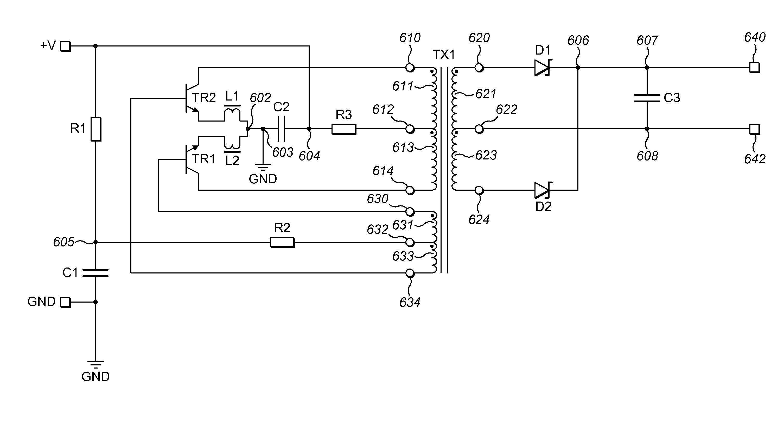
[0030]Preferred embodiments of the present invention include an embedded magnetic component transformer device including first, second, and auxiliary windings extending around a magnetic core embedded in a substrate. The embedded magnetic component transformer device may advantageously be used as a portion of switching power electronic devices, such as a Royer circuit. A first preferred embodiment of the present invention is illustrated in FIGS. 2 to 6 which will be discussed in detail below.

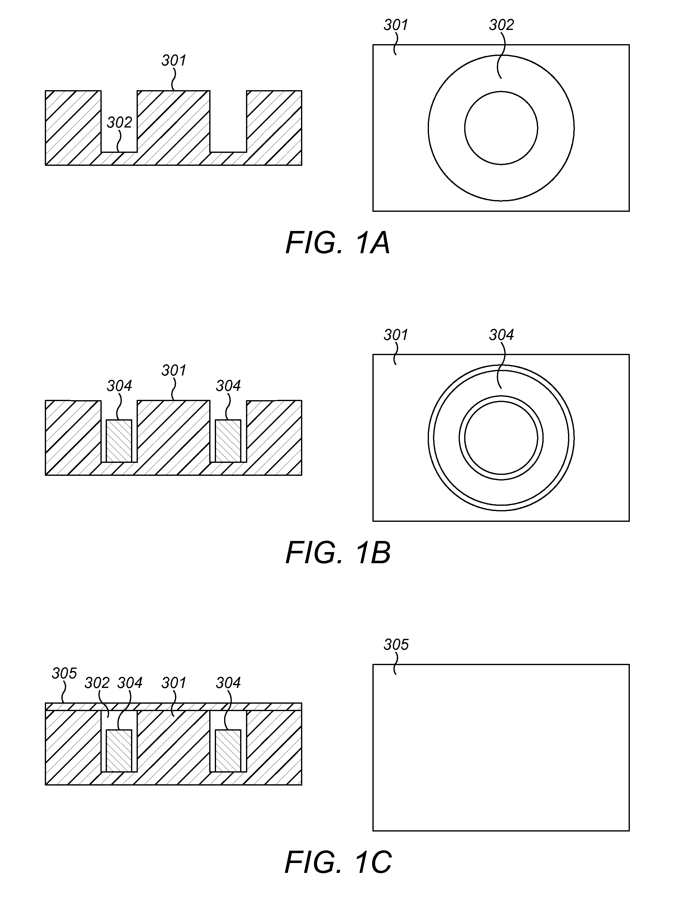
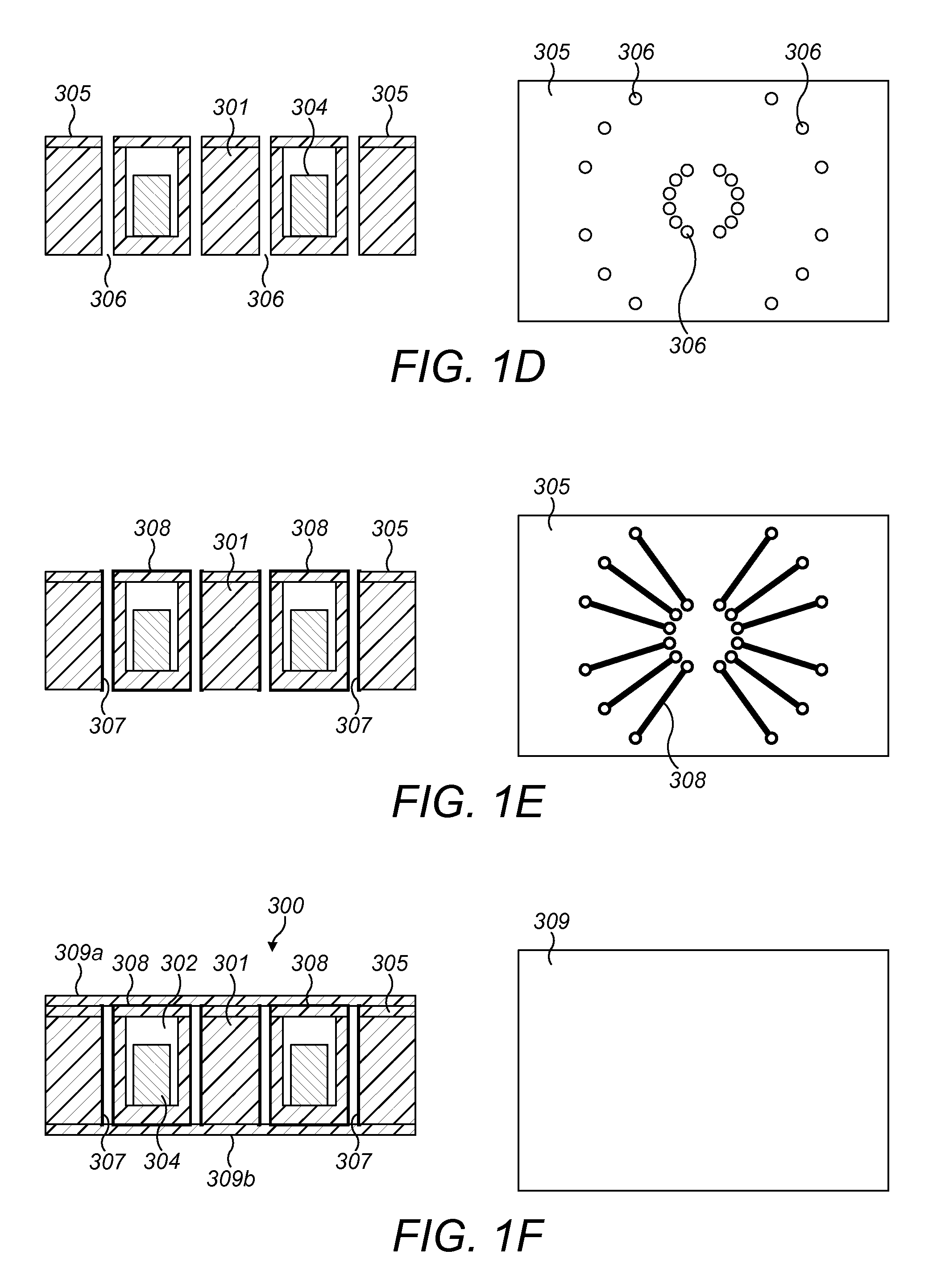
[0031]For ease of understanding, an example method of manufacturing an embedded magnetic component transformer device will now be described with reference to FIGS. 1A to 1F. Techniques for manufacturing an embedded magnetic component transformer device are described in UK patent applications GB 1414469.5 and GB 1414468.7 filed by the present applicant, the entire contents of which are incorporated herein by reference.

[0032]In a first step of the method, illustrated in FIG. 1A, a circular annulus...


PUM


Abstract

An embedded transformer device includes first, second, and auxiliary windings, defined in an insulating substrate by conductive vias joined together by conductive traces. The positions of the conductive vias are arranged to optimize the isolation properties of the transformer and to reduce the coupling of the transformer by increasing the leakage inductance. The embedded transformer device provides better isolation between input side and output side windings, and allows an oscillating LC circuit to be set up in the case of a short circuit, preventing high power from extending between the input and output terminals and thereby avoiding damage to the connected electrical components.

Description

BACKGROUND OF THE INVENTION[0001]1. Field of the Invention[0002]The present invention relates to an embedded magnetic component transformer device, and in particular to an embedded magnetic component transformer devices with reduced coupling and improved isolation properties.[0003]2. Description of the Related Art[0004]It is known, for example, in US 2011 / 0108317 A1, to provide low profile transformers and inductors in which the magnetic components are embedded in a cavity in a resin substrate, and the necessary input and output electrical connections for the transformer or inductor are formed on the substrate surface. A printed circuit board (PCB) for a power supply device can then be formed by adding layers of solder resist and copper plating to the top and / or bottom surfaces of the substrate. The necessary electronic components for the device may then be surface mounted on the PCB.[0005]Compared to conventional transformers, an embedded design allows a significantly thinner and m...

Claims


Application Information

Patent Timeline
IPC IPC(8): H02M3/335H01F27/24H01F41/04H01F27/28
CPCH02M3/33546H01F27/2804H01F2027/2809H01F41/041H01F27/24H02M3/33538H02M3/337H01F19/06Y02B70/10H02M1/0058H02M3/01H01F27/28H01F27/324H01F41/125
Inventor WANG, JINGKNELLER, QUINNPARISH, SCOTT
Owner MURATA MFG CO LTD
Why Eureka
Try Eureka