
Electrical circuit for delivering power to consumer electronic devices

a technology of electric circuits and electronic devices, applied in the direction of instruments, process and machine control, code conversion, etc., can solve the problems of increasing the energy crisis worldwide, wasting electricity, and not accomplishing anything, so as to reduce conduction and switching losses, and reduce resistance.

Active Publication Date: 2016-04-28
SMART PRONG TECH INC
View PDF7 Cites 73 Cited by
  • Summary
  • Abstract
  • Description
  • Claims
  • Application Information

AI Technical Summary

Benefits of technology

The patent text explains that a BCDMOS process can be used to make power circuits on a single chip that can handle high voltages. This process combines the functions of bipolar, CMOS, and DMOS transistors, making it ideal for applications such as LED lighting and AC-DC conversion. It also allows for the use of low-resistance, high-breakdown voltage components that can improve efficiency and reduce losses in power switching applications.

Problems solved by technology

All this means that even when a cell phone, lap top or like device is completely charged, current is still flowing, but not accomplishing anything and wasting electricity.
More recently manufactured devices and appliances continue to draw current all day, every day—and cost you money and add to the Energy Crisis Worldwide.
“The impact of plug loads on overall consumption is quite significant.
One of the problems experienced by virtually all modern electronics is that power supplies, whether external or embedded “power modules”, are not energy efficient.
Transformers are inherently inefficient because, as an analog device, they can only produce one power output for each specific winding.
Moreover, there are often over 50 parts and pieces that are necessary to work with a transformer to create a common modern external power supply, the numbers only get somewhat lower with internal or embedded power modules.
The number of parts in a power supply is inherently inefficient because current must travel in, around and through the various parts, each with different power dissipation factors; and even the circuit traces cause resistive losses creating energy waste.
Further, the way a transformer works is creating and collapsing a magnetic field.
It is also the primary reason why all consumer electronics create heat, which not only wastes energy / electricity, but causes eventual detrition through heating of other associated electronic parts.
Another inefficiency found in current electronics is the need for multiple internal power supplies to run the different parts.
However, most often the microprocessor and the drivers for the MOSFETS operate at different voltages, causing the need for multiple power supplies within a common electrical device circuit.
In addition to the heat problem, the multiple transformer based power supplies all need typically from forty to sixty parts to operate, requiring dozens of parts for a typical transformer based television power supply module which increases costs and total component size while decreasing reliability.
With the multiplicity of parts comes increased system resistance which ends up in wasted energy as heat.

Method used


Image

  • Electrical circuit for delivering power to consumer electronic devices
  • Electrical circuit for delivering power to consumer electronic devices
  • Electrical circuit for delivering power to consumer electronic devices

Examples


Embodiment Construction

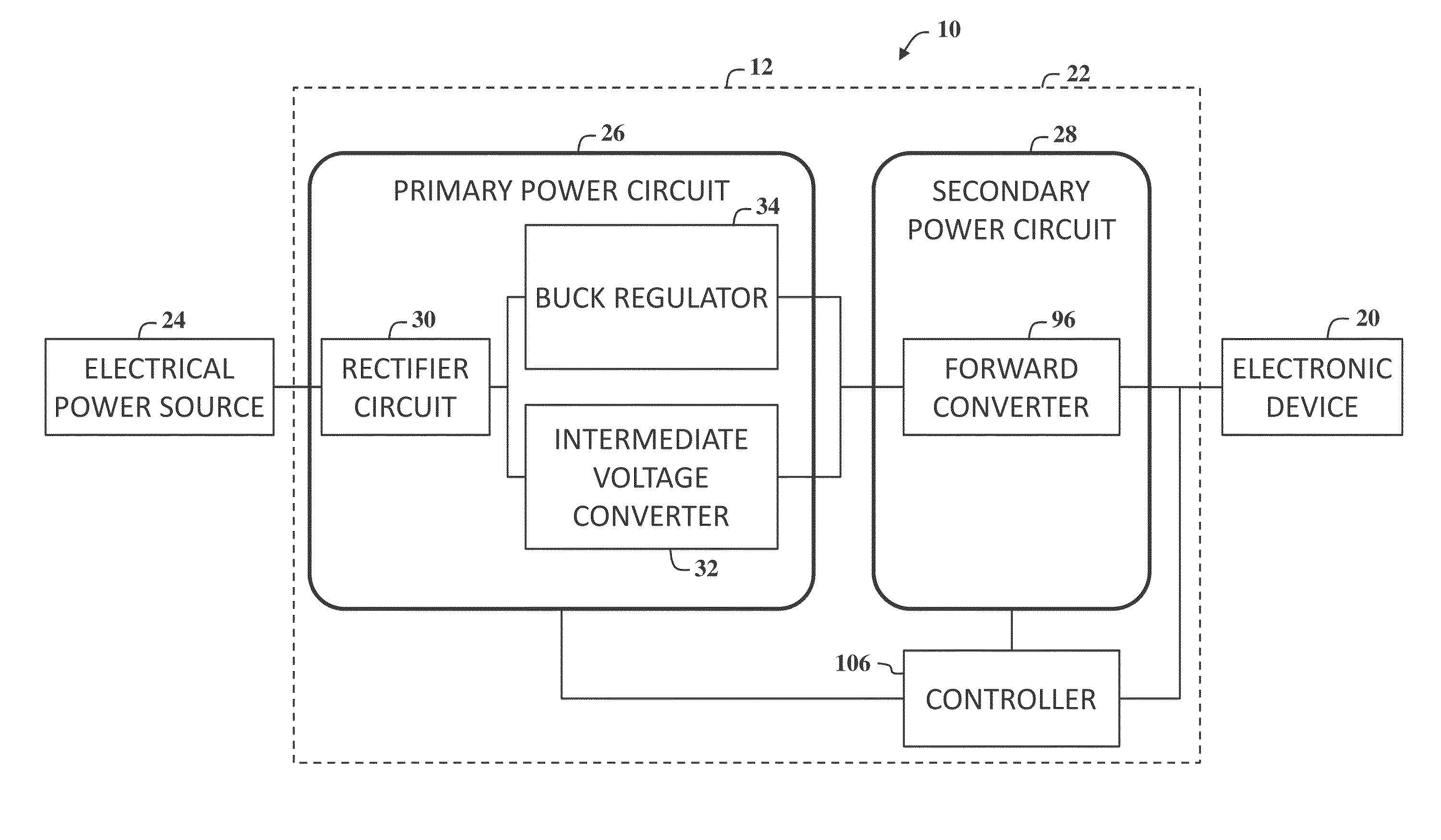
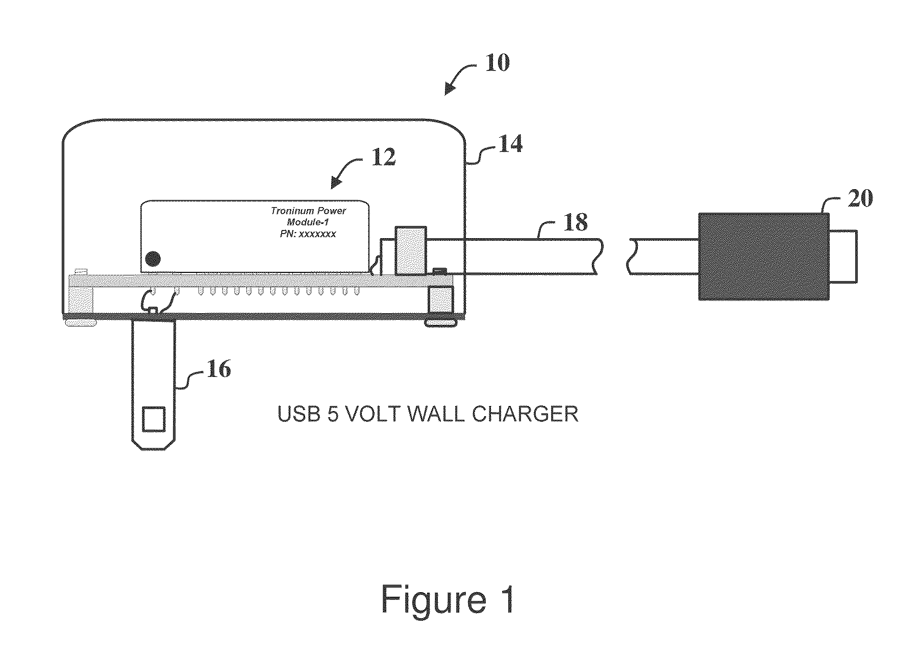
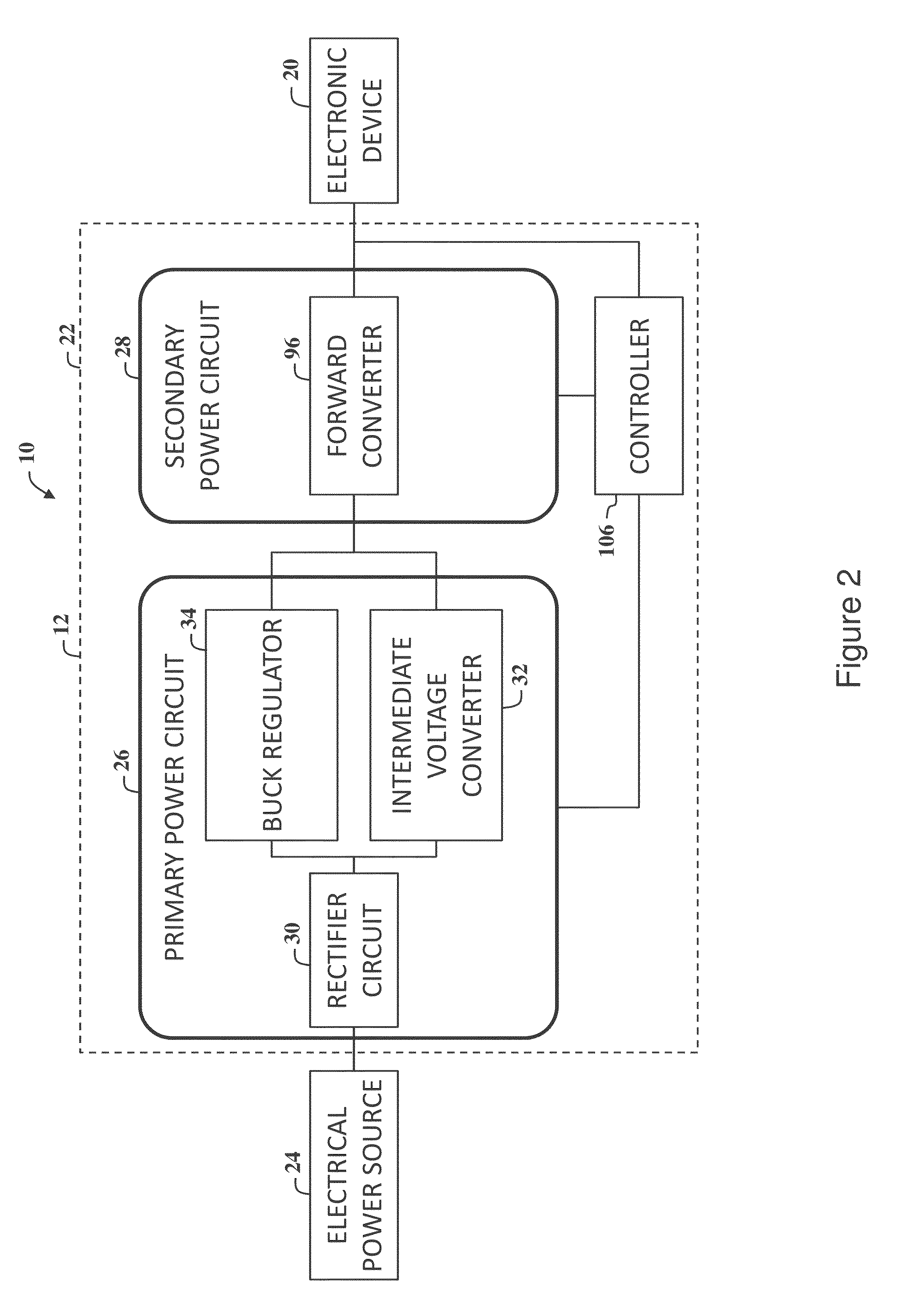
[0099]With reference to the drawings and in operation, the present invention overcomes at least some of the disadvantages of known power delivery systems by providing a power module that includes a power circuit that provides DC voltage output power to consumer electronic devices from an AC mains supply (typically 120 VAC (US) to 240 VAC[EU / Asia]). The power circuit is configured to provide electrical power to charge electronic storage devices and / or power consumer electronic products including, but not limited to, a cell phone, a smartphone, a tablet computer, a laptop, and / or any suitable electronic device that may benefit from this invention due to extremely high efficiencies and very low stand-by power requirements.

[0100]In an embodiment of the present invention, the power circuit includes a plurality of voltage reduction circuit cells, e.g., stages, that are configured to receive an input power signal and deliver an output power signal at a desired voltage level. In one embodim...


PUM


Abstract

An electrical circuit for providing electrical power for use in powering electronic devices, such as monitors, televisions, white goods, data centers, and telecom circuit boards, is described herein. The electrical circuit includes a voltage reduction circuit cell that includes a first capacitor, a second capacitor, a switching circuit, and a hold capacitor. The switching circuit includes a plurality of switching devices that are coupled to the first and the second capacitors for delivering power from an input terminal to an output terminal. The plurality of switching devices includes at least two switching devices that are coupled to ground. The voltage reduction circuit cell also includes a controller for operating the switching circuit in a plurality of operational modes to deliver an output power signal at a desired voltage level.

Description

CROSS-REFERENCES TO RELATED APPLICATIONS[0001]This application claims priority to U.S. Provisional Patent Application Ser. No. 62 / 069,672, filed on Oct. 28, 2014, claims priority to U.S. Provisional Patent Application Ser. No. 62 / 074,525, filed on Nov. 3, 2014, claims priority to U.S. Provisional Patent Application Ser. No. 62 / 094,884, filed on Dec. 19, 2014, claims priority to U.S. Provisional Patent Application Ser. No. 62 / 175,972, filed on Jun. 15, 2015, claims priority to U.S. Provisional Patent Application Ser. No. 62 / 180,549, filed on Jun. 16, 2015, claims priority to U.S. Provisional Patent Application Ser. No. 62 / 208,520, filed on Aug. 21, 2015, claims priority to U.S. Provisional Patent Application Ser. No. 62 / 236,731, filed on Oct. 2, 2015, all of which are hereby incorporated by reference in their entirety for all purposes.COPYRIGHT NOTICE[0002]The figures included herein contain material that is subject to copyright protection. The copyright owner has no objection to the...

Claims


Application Information

Patent Timeline
Patent Type & Authority Applications(United States)
IPC IPC(8): G05F1/46
CPCG05F1/462H02M1/08H02M1/32H02M1/36H02M3/073H02M3/156H02M3/33515H02M3/33553H02M7/06H02M3/07Y02B70/10H02M1/0025H02M1/0032H02M1/0045H02M1/007H02M3/075H02M3/072H03M7/10H02M1/0009H02M3/33546
Inventor FREEMAN, MICHAEL H.WEAVER, JR., W.J. "JIM"FREEMAN, MITCHAEL C.DIETER, ROBERTBASCHIROTTO, ANDREAMALCOVATI, PIEROGRASSI, MARCONOUFER, GLENNSANDUSKY, RANDALL L.FAROOQI, NEAZDEVOY, JIMJAECKEL, SILVIAFREEMAN, MADISON HAYES YARBRO
Owner SMART PRONG TECH INC
Learn More