
Semiconductor fabrication method

Inactive Publication Date: 2016-04-28
POWERCHIP TECH CORP
View PDF4 Cites 3 Cited by
  • Summary
  • Abstract
  • Description
  • Claims
  • Application Information

AI Technical Summary

Benefits of technology

The patent describes an improved way to make semiconductors. It involves putting a layer of material called a "material layer" on top of a substrate with semiconductor elements. The material layer is then etched to expose the semiconductor elements. A "pattern" is formed by removing a portion of the material layer using a process called exposure and development. The pattern is polished. The material layer is made of a photosensitive polymeric material with high refractive index and low extinction coefficient. This method helps to create precise and reliable semiconductor devices.

Problems solved by technology

As the resolution of a CMOS image sensor increases, the size of each pixel sensor in the image sensor shrinks, which may also lead to the decreasing of the size of the photosensitive element (e.g., photodiode) in each pixel sensor.
This becomes problematic when high sensitivity is required.
However, conventional lightpipe fabrication processes often lead to depth fluctuations and thickness variations for the lightpipes in the CMOS sensor.

Method used


Image

  • Semiconductor fabrication method
  • Semiconductor fabrication method
  • Semiconductor fabrication method

Examples


Embodiment Construction

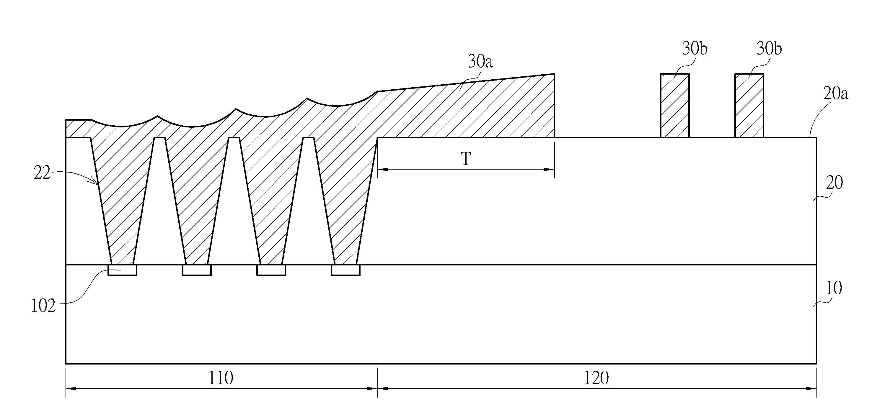
[0016]In the following detailed description of the invention, reference is made to the accompanying drawings which form a part hereof, and in which is shown, by way of illustration, specific embodiments in which the invention may be practiced. These embodiments are described in sufficient detail to enable those skilled in the art to practice the invention. Other embodiments may be utilized and structural, logical, and electrical changes may be made without departing from the scope of the present invention. The following detailed description is, therefore, not to be taken in a limiting sense, and the scope of the present invention is defined by the appended claims.

[0017]The terms wafer and substrate used herein include any structure having an exposed surface onto which a layer is deposited according to the present invention, for example, to form the integrated circuit (IC) structure. The term substrate is understood to include semiconductor wafers. The term substrate is also used to ...


PUM


Abstract

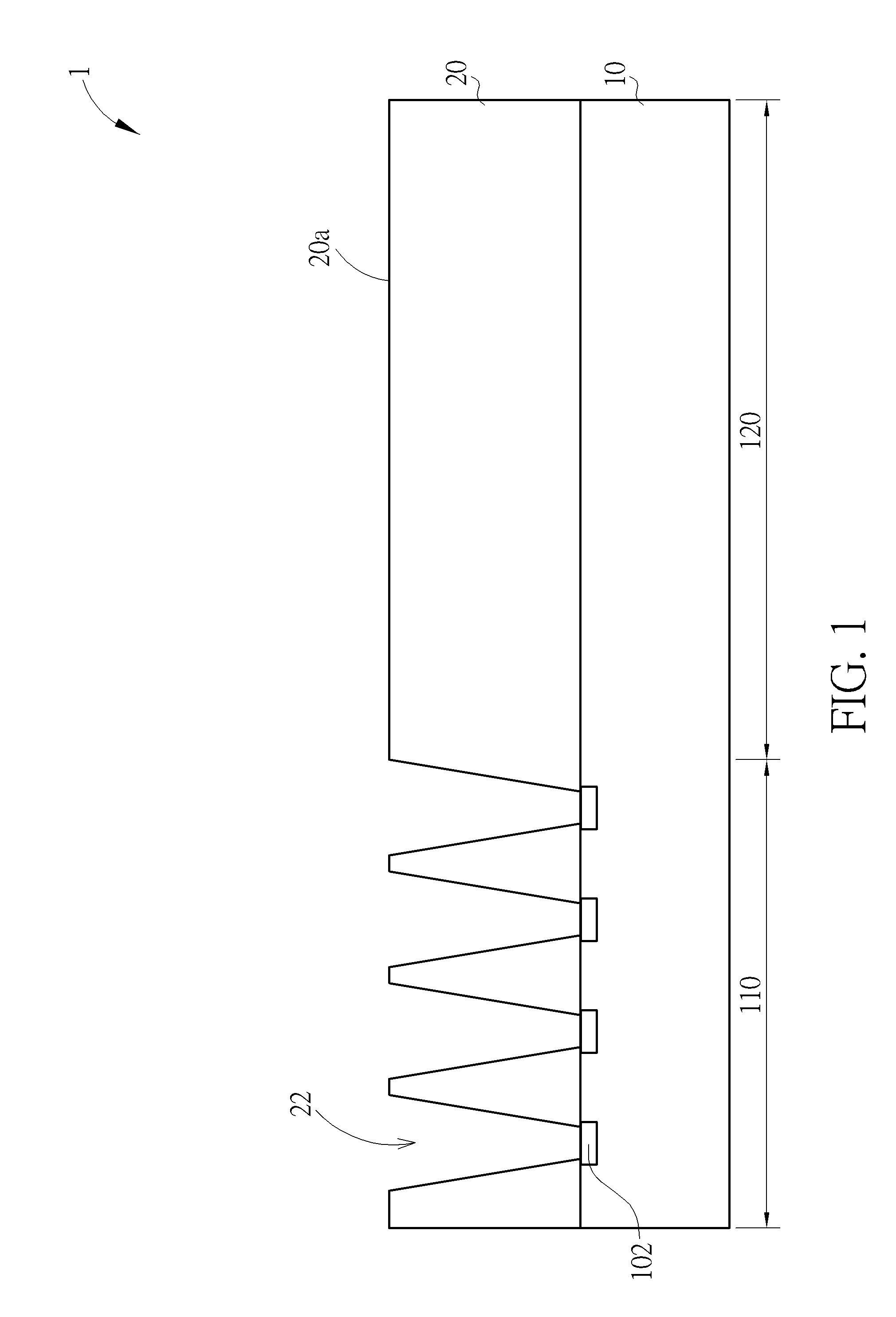
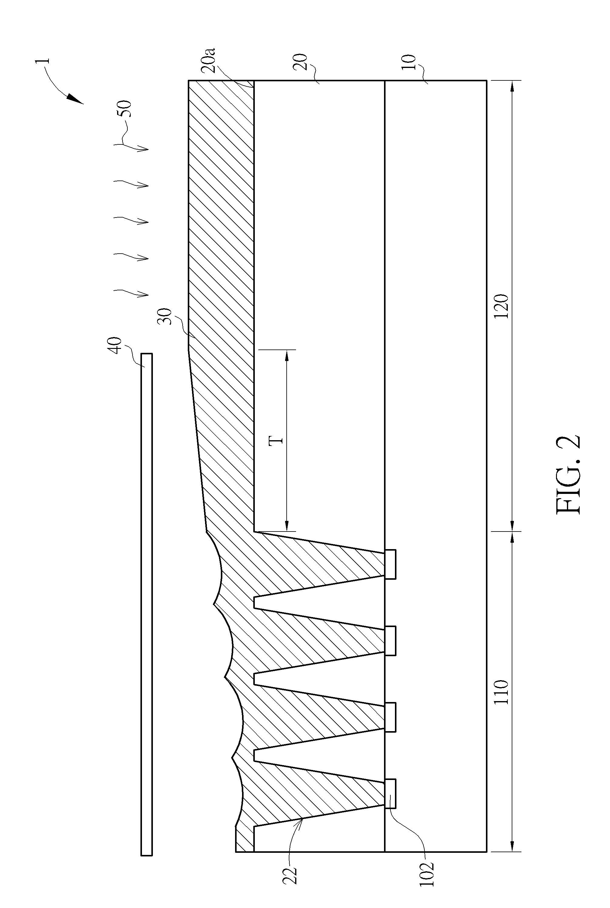
A semiconductor fabrication method is disclosed. A substrate having thereon a plurality of semiconductor elements are provided. A dielectric layer is formed on the substrate. A plurality of openings is etched into the dielectric layer to respectively reveal the semiconductor elements. A material layer is coated on the substrate and the material layer fills into the openings. The material layer is then subjected to exposure and development processes to remove a portion of the material layer, thereby forming a material pattern. The material pattern is then polished by chemical mechanical polishing.

Description

CROSS REFERENCE TO RELATED APPLICATION[0001]This application claims the benefit of Taiwan patent application No. 103136845, filed on Oct. 24, 2014, the disclosure of which is incorporated herein in its entirety by reference.BACKGROUND OF THE INVENTION[0002]1. Field of the Invention[0003]The present invention relates to a semiconductor fabrication method and, more particularly, to a back-end-of-line (BEOL) method for fabricating CMOS image sensors.[0004]2. Description of the Prior Art[0005]As the development of electronic products such as digital cameras and scanners progresses, the demand for image sensors increases accordingly. In general, image sensors in common usage nowadays are divided into two main categories: charge coupled device (CCD) sensors and CMOS image sensors (CIS). Primarily, CMOS image sensors have certain advantages of low operating voltage, low power consumption, and an ability for random access. Furthermore, CMOS image sensors are currently capable of integration...

Claims


Application Information

Patent Timeline
IPC IPC(8): H01L27/146
CPCH01L27/14689H01L27/14685
Inventor CHUNG, TSE-WEICHOU, TSUNG-HUILAI, YU-YUAN
Owner POWERCHIP TECH CORP
Learn More