Method and Device for the Adjustment of Contactless Data Links

a technology of contactless data and adjustment method, applied in the field of contactless data link, to achieve the effect of omitting unnecessary steps, low bit error rate, and easy adjustmen

Active Publication Date: 2016-05-05
SCHLEIFRING & APPBAU
View PDF13 Cites 9 Cited by
  • Summary
  • Abstract
  • Description
  • Claims
  • Application Information

AI Technical Summary

Benefits of technology

[0019]Preferably, step a) is performed as the first step, as the height is mainly determined by mechanical characteristics, such that the transmitter never touches the receiver during operation, which may result in damage of the parts. The further steps b) to e) may be performed in any order. It is preferred, if for each of these further adjustment steps, the settings are adjusted in small steps and the resulting signal quality or bit error rate is measured. Based on this result, the best setting may be calculated. It may be beneficial to iterate steps b) to e) to obtain the best result. It may further be beneficial to include step a) into iteration. This may avoid the receiver approaching the transmitter too close. It may be possible to omit unnecessary steps. Preferably step b) is omitted, as this kind of alignment may easily be done by the mechanical design of the receiver.
[0020]As well adjusted data links have very low bit error rat...

Problems solved by technology

Another problem to be solved is to provide means and methods for adjusting a contactless data l...

Method used


Image

  • Method and Device for the Adjustment of Contactless Data Links
  • Method and Device for the Adjustment of Contactless Data Links
  • Method and Device for the Adjustment of Contactless Data Links

Examples


Embodiment Construction

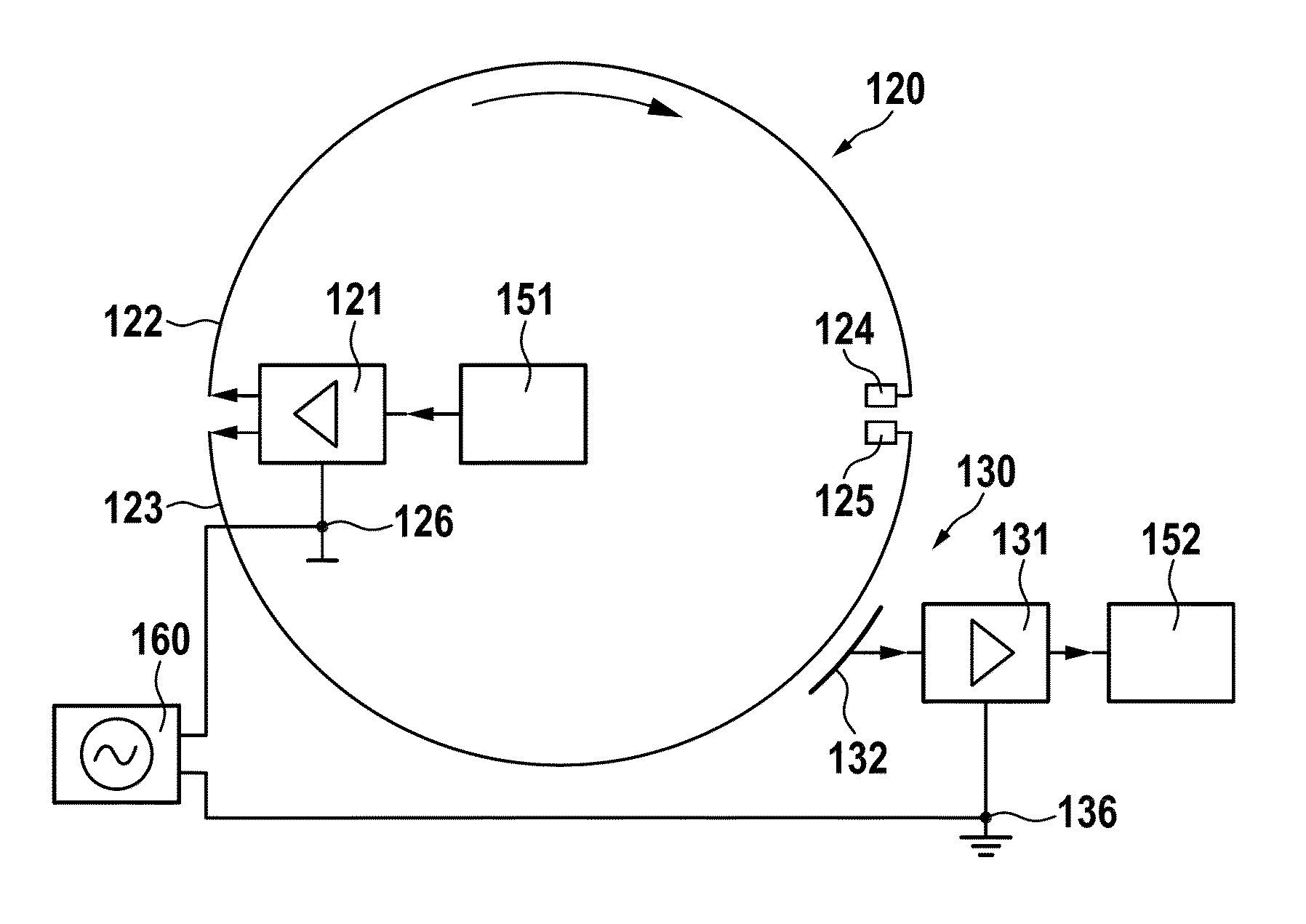
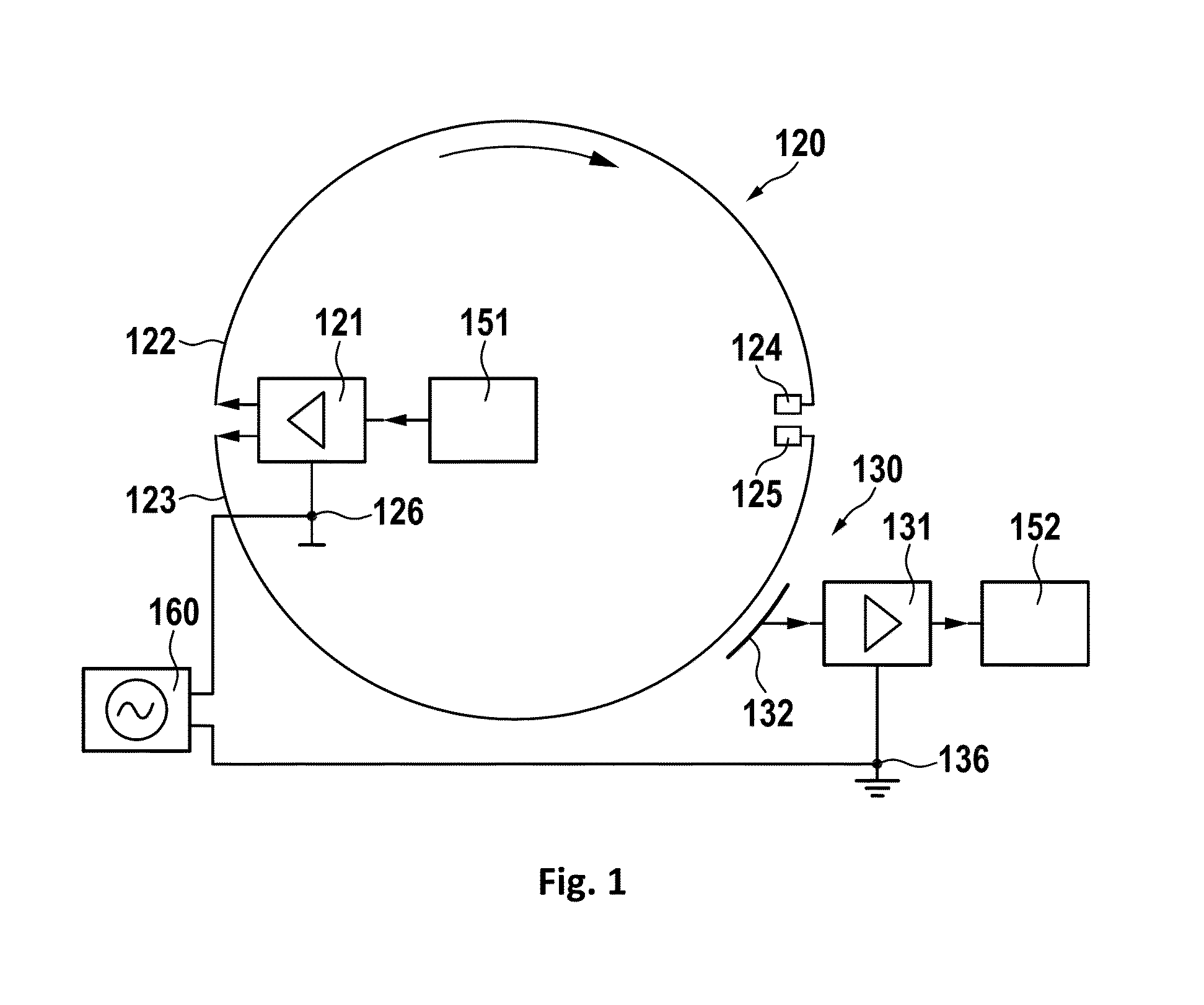
[0037]In FIG. 1, a preferred embodiment is shown. The contactless rotary joint has a transmitter 120 and a receiver 130. A data source 151 generating a test pattern which preferably is a pseudo-noise pattern is coupled to a transmitter amplifier 121 which is part of the transmitter 120. The transmitter amplifier is generating signals for driving the transmission lines 122, 123. These are terminated by terminators 124, 125. Preferably, the transmission lines 122, 123 have the same length and enclose half of the circumference of the rotating part of the rotary joint. It is further preferred, if the terminators 124, 125 are opposite to the position to where the transmitter amplifier 121 is connected to the transmission lines 122, 123. As will be shown later, each of the transmission lines 122, 123 is a differential line comprising two transmitter conductors 127, 128 which are driven by a differential signal.

[0038]A receiver 130 is mounted in close proximity to the transmitter 120 and h...


PUM


Abstract

A test setup for testing a contactless digital rotary joint integrated in a device requiring data transmission between a rotating part and a stationary part, the rotary joint further comprises a transmitter and a receiver. The transmitter has a transmitter amplifier, which is coupled to a pair of transmission lines, which are terminated by a pair of terminations. The transmission lines are differential transmission lines comprising a pair of conductors which is driven by differential signals from the transmitter amplifier. The receiver has a receiver antenna comprising a pair of antenna sections which are differentially operated and feed a differential signal to the receiver amplifier. A transmitter ground and a receiver ground are coupled to a common mode signal generator generating a common mode signal. A data source is coupled to the transmitter amplifier feeding a test signal into the transmitter amplifier, and a data sink is coupled to the receiver amplifier for receiving the test signal and generating a test result value. Also disclosed is a method for adjusting a contactless data link integrated in a device requiring data transmission between a rotating part and a stationary part.

Description

PRIORITY CLAIM[0001]This application claims priority to pending European Application No. 14191716.1 filed on Nov. 4, 2014, which is incorporated herein by reference in its entirety.BACKGROUND OF THE INVENTION[0002]1. Field of the Invention[0003]The invention relates to contactless data links which are used for transmission of high frequency signals or data between units movable against each other, which for example are rotating units like rotary joints. These contactless data links have to be adjusted or the adjustment has to be checked to meet the requirements of EMC standards, and to obtain a high data rate, high reliability, and low transmission losses or bit error rates. These adjustment procedures require specific tools and must be adapted to the contactless data links.[0004]2. Description of Relevant Art[0005]A contactless data link is disclosed in the U.S. Pat. No. 6,301,324 B1. This contactless data link is also called a contactless slip ring. It has a circular-shaped transm...

Claims


Application Information

Patent Timeline
IPC IPC(8): H04B17/00A61B6/03A61B6/00H04B17/309
CPCH04B17/0085H04B17/309A61B6/5258A61B6/56A61B6/032A61B6/035H04B5/0031H04B5/0037H04B17/104H04B17/14H04B17/16H04B17/21H04B17/27
Inventor STEFFENS, HOLGER
Owner SCHLEIFRING & APPBAU
Why Eureka
Try Eureka