Tilt Detecting System And Tilt Detecting Method

a detection system and tilt technology, applied in the direction of reference lines/planes/sectors, movable markers, instruments, etc., can solve the problems of high accuracy, high response speed, and the size of the detector must be increased in proportion, so as to improve the accuracy of photogrammetry by flying objects, the effect of improving the working efficiency and high accuracy

Active Publication Date: 2016-05-12
KK TOPCON
View PDF9 Cites 11 Cited by
  • Summary
  • Abstract
  • Description
  • Claims
  • Application Information

AI Technical Summary

Benefits of technology

[0022]Further, according to the present invention, in the tilt detecting system, the surveying instrument further has a tracking function, the surveying instrument projects a tracking light and tracks the photodetection device based on the tracking light reflected by the target. As a result, there is no need to manually direct the surveying instrument towards the photodetection device, and this contributes to the improvement of the working efficiency.
[0023]Further, according to the present invention, in the tilt detecting system, the photodetection device further comprises a pole for supporting the photodetection device and a two-dimensional directional sensor for receiving the tracking light of the surveying instrument and detects an inclining angle in an approaching and separating direction with respect to the surveying instrument and a rotation angle around a centerline of the pole as a center. As a result, it is possible to correct a three-dimensional position of the photodetection device with high accuracy.
[0024]Further, according to the present invention, in the tilt detecting system, the photodetection device is provided on a flying object, the surveying instrument has a tracking function, the surveying instrument measures a position of the flying object, and corrects the position of the flying object based on a tilting angle of the photodetection device. As a result, an accuracy of photogrammetry by the flying object can be improved.
[0025]Further, according to the present invention, in the tilt detecting system, the photodetection device has at least three photodetection units and wherein the line laser projecting unit is rotated at a known speed and the line laser is scanned by each photodetection unit, and the arithmetic unit detects a tilting angle of the photodetection device based on a deviation of photodetection time between another photodetection unit and one of the photodetection units as reference and a deviation of photodetection time between the other photodetection unit and the one as reference. As a result, there is no need for

Problems solved by technology

In order to keep the measurement range as desired, there has been a problem in that the size of the detectors must be increased in proportion to the interval between the two detectors.
Further, conventionally, detecting of a tilting angle with respect to horizontal and vertical lines are possible, b

Method used


Image

  • Tilt Detecting System And Tilt Detecting Method
  • Tilt Detecting System And Tilt Detecting Method
  • Tilt Detecting System And Tilt Detecting Method

Examples


first embodiment

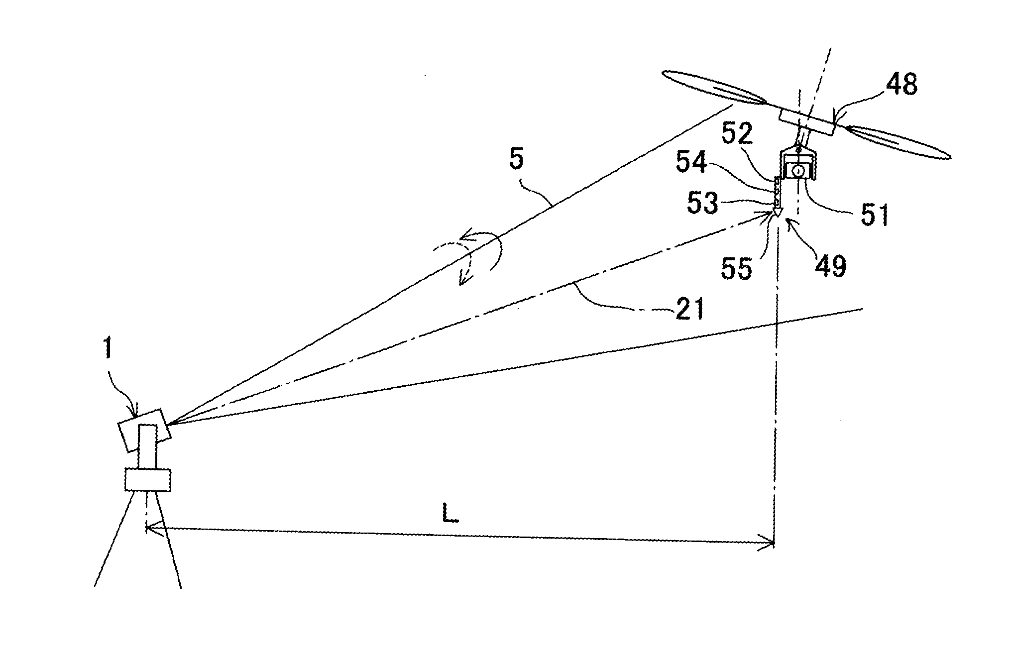
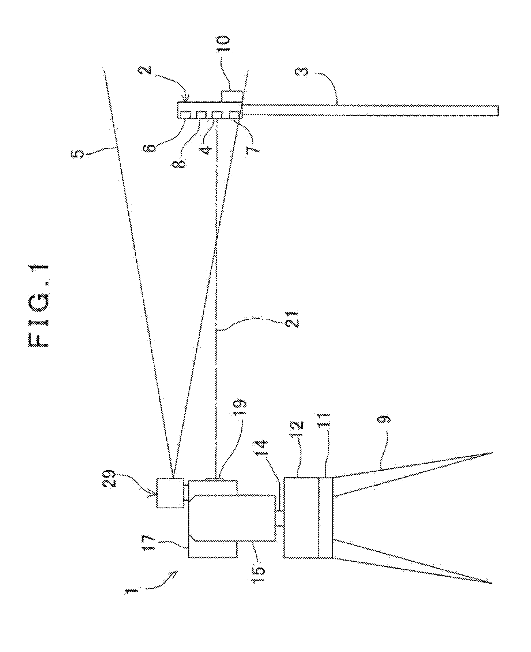
[0039]First, referring to FIG. 1, a description will be given on a distance measuring system according to the present invention.

[0040]In FIG. 1, reference numeral 1 denotes a surveying instrument having a tilt detecting mechanism, a total station, for instance.

[0041]Within a measurement range of the surveying instrument 1, a photodetection device 2 in cylindrical shape is erected. The photodetection device 2 is installed at an upper end of a supporting member as required (shows a pole 3 in the figure) such as a pole, a tripod, etc. The photodetection device 2 has a target 4 having retro-reflectivity such as a corner cube, a reflection sheet, etc. A height of the target 4, i.e. the height from a lower end of the pole 3, is already known.

[0042]Further, on the photodetection device 2, a first photodetection sensor 6 as a first photodetection unit and a second photodetection sensor 7 as a second photodetection unit which are able to receive a line laser 5 (to be described later) spreadi...

second embodiment

[0071]Next, by referring to FIG. 1 and FIG. 4, description will be given on the present invention.

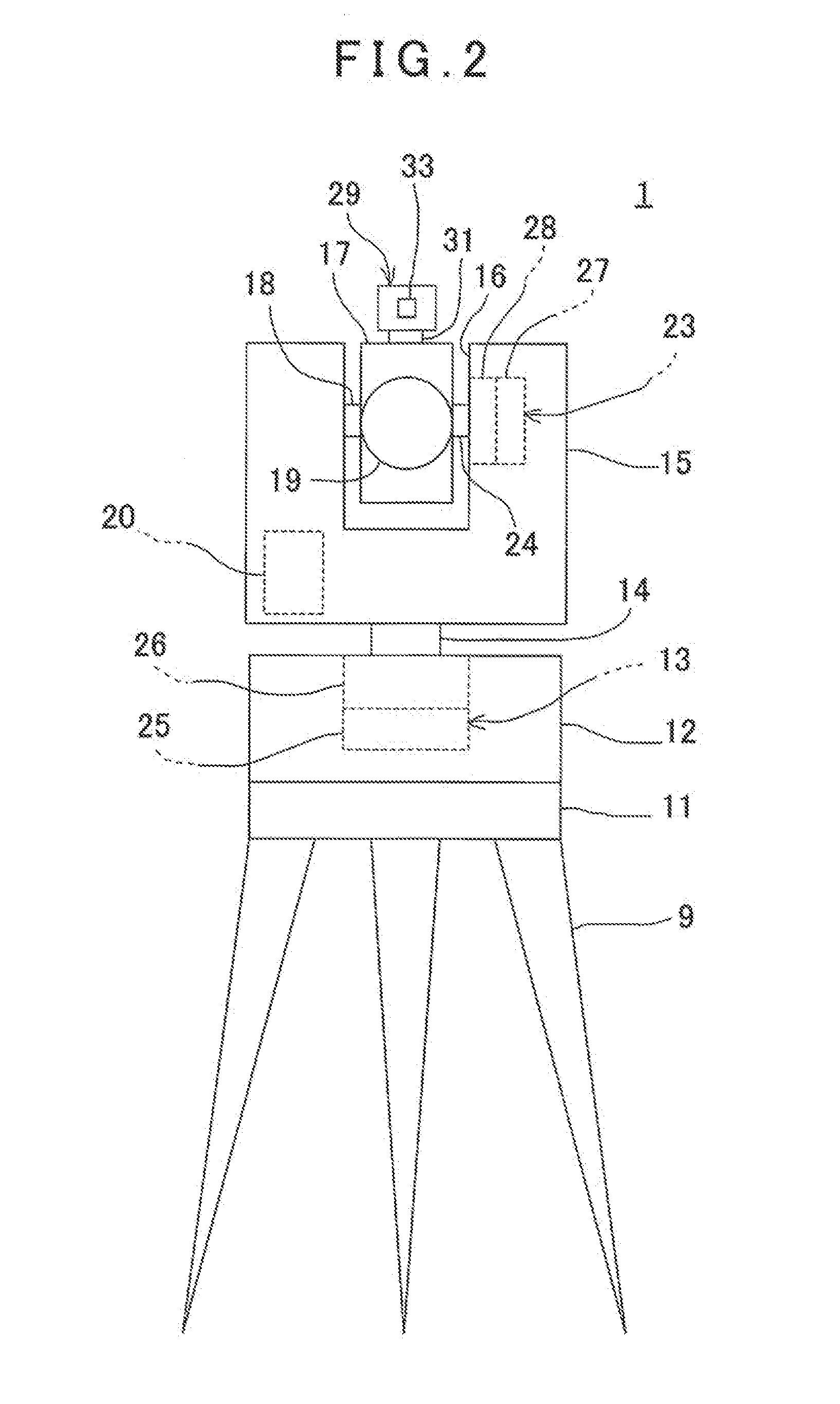
[0072]In the second embodiment, under a condition where a telescope unit 17 tracks a target 4, a line laser projecting unit 29 is reciprocated around a tracking optical axis as a center at a low speed and at a constant speed within the range of a predetermined angle, e.g. 1° to 2° for instance, so that a line laser 5 can be received a plurality of times by a first photodetection sensor 6 and a second photodetection sensor 7.

[0073]It is to be noted that FIG. 4 shows a condition that the line laser 5 is received two times (i.e. in one round trip) by the first photodetection sensor 6 and the second photodetection sensor 7. Further, in FIG. 4, reference numeral 36 denotes a photodetection signal waveform of a first course (i.e. outward course) and reference numeral 37 denotes the photodetection signal waveform of a second course (i.e. return course).

[0074]A detection accuracy of a tilting a...

third embodiment

[0082]Next, by referring to FIG. 5 and FIG. 6, a description will be given on the present invention. In FIG. 5, the same component as shown in FIG. 1 and FIG. 2 is referred by the same symbol, and detailed description is omitted.

[0083]In the third embodiment, a diffraction grating 38 is provided on an emitting side of a cylindrical lens 33. By the diffraction grating 38, a line laser 5 is divided by a predetermined diffraction pitch (a predetermined angular pitch) “b” to three line lasers 5a to 5c which have an interval of 10°, for instance.

[0084]The detection accuracy of the tilting angle depends on a stability of a scanning angle speed, and it is necessary to detect the scanning angle speed of a case where a line laser projecting unit 29 is rotated at a constant speed or the scanning angle speed when a first photodetection sensor 6 (see FIG. 1) and a second photodetection sensor 7 (see FIG. 1) receive the line laser 5.

[0085]In the third embodiment, by the diffraction grating 38, p...


PUM


Abstract

The invention provides a tilt detecting system comprising, a surveying instrument having a distance measuring function and a line laser projecting unit installed as horizontally rotatable for projecting a vertical line laser, and a photodetection device having at least two photodetection units provided at a known interval, a target with a retro-reflectivity and an arithmetic unit, wherein the line laser projecting unit is rotated, each of the photodetection units are made to scan the line laser and the arithmetic unit detects a tilting angle of the photodetection device based on a deviation between a photodetection time moment of each photodetection unit and the distance measurement result of the target of the surveying instrument.

Description

BACKGROUND OF THE INVENTION[0001]The present invention relates to a tilt detecting system and a tilt detecting method, by which a tilt of a photodetection device can be detected.[0002]As a method for distance measurement to a measuring point, there is a method for measuring a distance to a measuring point, in which a target having retro-reflectivity is installed on a measuring point and a target is measured by a surveying instrument such as a total station.[0003]Normally, a target is provided at an upper end of a pole and a lower end of the pole is installed at a measuring point. In order to accurately measure a distance to the measuring point, it is necessary for the target to be positioned just above the measuring point. In case the pole is tilted, it is necessary to detect a tilting angle of the pole and to correct the position of the target.[0004]Conventionally, a laser plane is generated by rotary irradiation of a laser beam from a surveying instrument main unit along a referen...

Claims


Application Information

Patent Timeline
IPC IPC(8): G01C15/00G01C5/00
CPCG01C5/00G01C15/004G01C15/06G01C15/002
Inventor KUMAGAI, KAORUOHTOMO, FUMIO
Owner KK TOPCON
Why Eureka
Try Eureka