
Adhesive contamination resistant web processing unit

a technology of contamination resistance and processing unit, applied in the field of processing webs, can solve the problems of high level of super absorbent material, difficult control and maintenance, and inability to remove complex and expensive equipment, so as to reduce the areas experiencing adhesive contamination, reduce the amount of adhesive contamination, and eliminate the effect of complex and expensive equipmen

Inactive Publication Date: 2016-05-19
CURT G JOA
View PDF9 Cites 6 Cited by
  • Summary
  • Abstract
  • Description
  • Claims
  • Application Information

AI Technical Summary

Benefits of technology

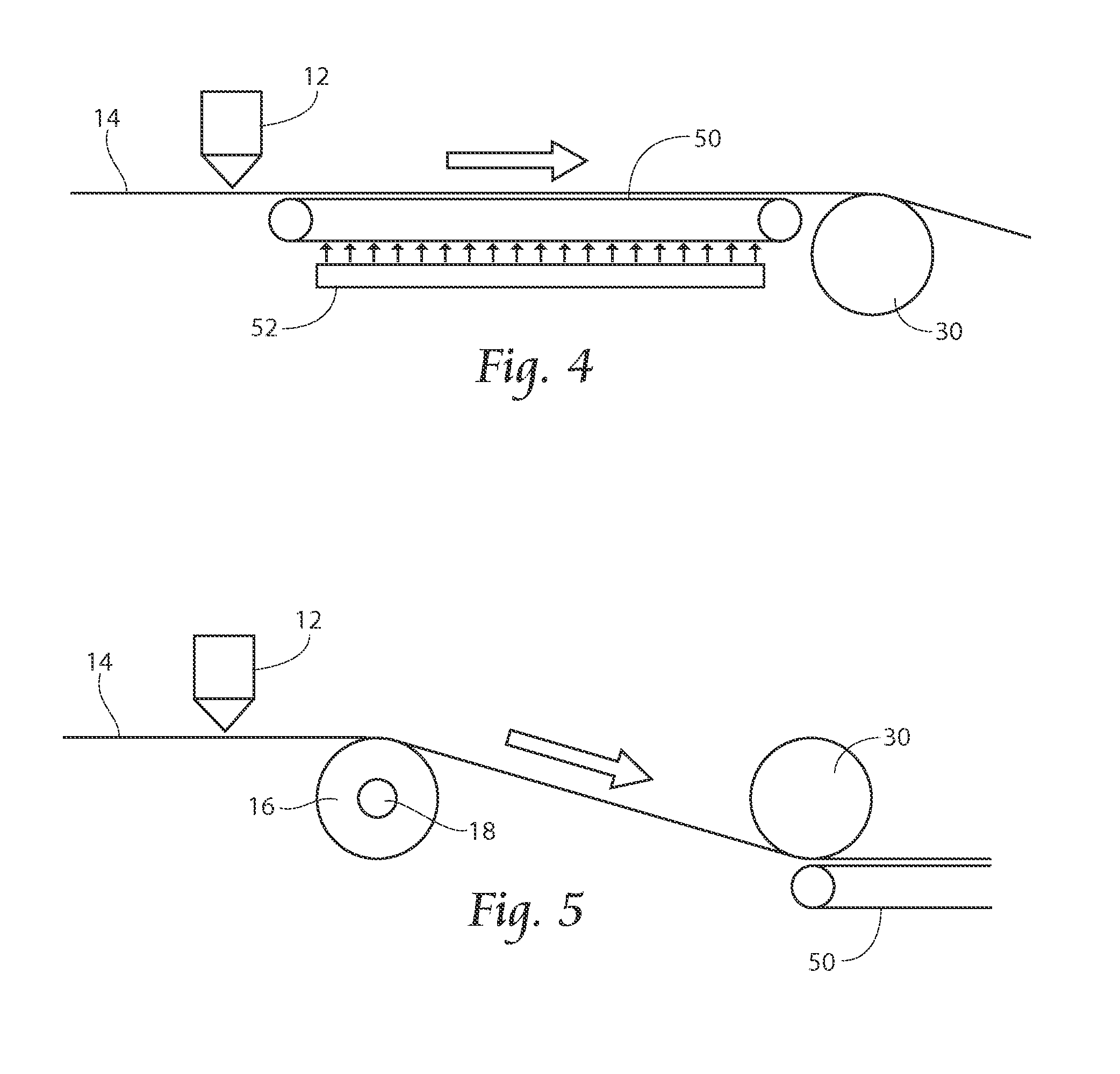
The invention is about a way to reduce adhesive buildup on processing surfaces and rollers in web processing units. One way is to use heated conveying surfaces and rollers that help prevent adhesive accumulation. This reduces the need for expensive and complex equipment to cool down the knives used in processing. Heat can also be applied intermittently to areas that are experiencing adhesive contamination. This way, the heat helps to carry the adhesive downstream, improving the overall processing efficiency.

Problems solved by technology

This complicates the removal of the chip because the severing might not create a continuous cut out chip, with possibly some strands of the web material still coupling the chip with the web.
High levels of super absorbent material, however, tend to be more difficult to control and to maintain in position.
Thus, some fluff undesirably becomes entrained in the vacuum stream.
Machine processes have become more complex as speeds of machines have increased, so air handling systems used in this process have greater demands placed on them.
One complication is in achieving optimum balance between air in to the pocket and vacuum applied to the back side of the pocket.
Conventional core forming technology allows for limited adjustability to try and achieve the optimum balance between air in and vacuum.
Below the web there is usually a roller or conveying belt and the adhesive that passes through the web undesirably accumulates on these surfaces.

Method used


Image

  • Adhesive contamination resistant web processing unit
  • Adhesive contamination resistant web processing unit
  • Adhesive contamination resistant web processing unit

Examples


Embodiment Construction

[0036]Although the disclosure hereof is detailed and exact to enable those skilled in the art to practice the invention, the physical embodiments herein disclosed merely exemplify the invention which may be embodied in other specific structures. While the preferred embodiment has been described, the details may be changed without departing from the invention.

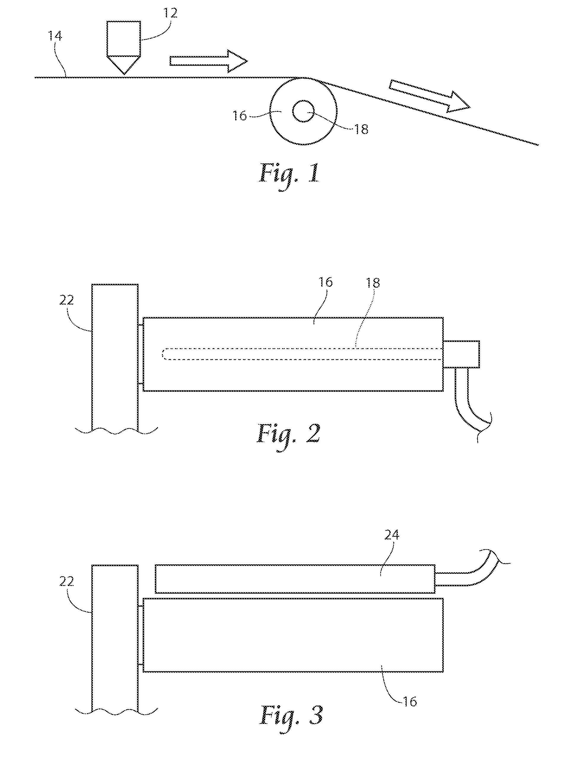
[0037]Referring now to FIG. 1, a heated, roller 16 carrying a nonwoven web 14 applied with adhesive by adhesive applicator 12 is shown.

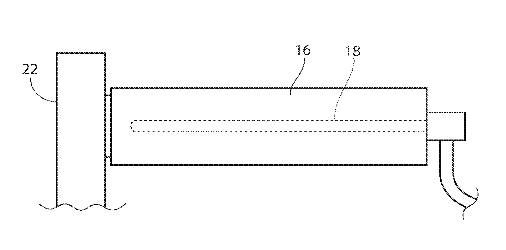
[0038]Referring now to FIG. 2, a heater cartridge 18

[0039]powered by electrical leads is shown embedded in rotating cylinder or roller 16, which is carried by a mount 22. As shown in FIG. 3, instead of a heater cartridge 18, an induction unit 24 can be positioned proximally to the roller 16.

[0040]FIG. 3 is a side view of an alternative embodiment of a heated structure.

Experiments

[0041]A cartridge heater was used to heat an approximately 1″ diameter roller in three conditions: 1) plasma coated; 2)...


PUM

PropertyMeasurementUnit
adhesive accumulation resistant temperatureaaaaaaaaaa
temperatureaaaaaaaaaa

Abstract

Heat is supplied to elements of a web processing system to resist adhesive contamination by buildup. A variety of heat sources can be used on a variety of web handling structures, such as rollers, idlers, conveyors, vacuum belts, or any other place where adhesive accumulation is undesired.

Description

RELATED APPLICATION[0001]This application claims the benefit of co-pending U.S. Provisional Patent Application Ser. No. 62 / 080,613, filed 17 Nov. 2014.BACKGROUND OF THE INVENTION[0002]This invention relates to processing webs of material for use in disposable products such as diapers and sanitary napkins. In particular, this invention relates to preventing buildup of adhesive materials on web processing equipment.[0003]Generally, diapers comprise an absorbent insert or patch and a chassis, which, when the diaper is worn, supports the insert proximate a wearer's body. Additionally, diapers may include other various patches, such as tape tab patches, reusable fasteners and the like. The raw materials used in forming a representative insert are typically cellulose pulp, tissue paper, poly, nonwoven web, acquisition, and elastic, although application specific materials are sometimes utilized. Usually, most of the insert raw materials are provided in roll form, and unwound and applied in...

Claims


Application Information

Patent Timeline
Patent Type & Authority Applications(United States)
IPC IPC(8): B65H23/26A61F13/15B65H20/06
CPCA61F13/15804A61F13/15699A61F13/15577B65H20/06A61F2013/15967B65H23/26A61F2013/15821B65H27/00B65H2301/5143B65H2701/1924B65H37/02B65H2515/40B65H2801/57
Inventor HAHN, MICHAEL T.MELIS, JAMES K.YLITALO, CLINTON H.INGOLE, SUDEEP
Owner CURT G JOA
Learn More