High power reciprocating pump manifold and valve cartridges

a technology of high-power reciprocating and manifold, which is applied in the direction of machines/engines, liquid fuel engines, positive-displacement liquid engines, etc., can solve the problems of large plungers and valves with ultimately higher dynamic loads, cumbersome arrangement, and many new challenges, and achieves easy removal and replacement, easy fabrication, and long service life.

Active Publication Date: 2016-05-19
FEDERAL SIGNAL CORPORATION
View PDF2 Cites 1 Cited by
  • Summary
  • Abstract
  • Description
  • Claims
  • Application Information

AI Technical Summary

Benefits of technology

[0005]Accordingly an objective of the concepts provided in this disclosure is to improve the valve cartridge on dynamic loads, to enable easier fabrication and to provide a more durable configuration. Another objective is to provide a manifold to house different sizes of valve cartridges for higher flow or higher pressure from the demand of higher power, and particularly for pumps meeting or exceeding 600 horsepower. In accord with the above, the pre

Problems solved by technology

Such an arrangement can be cumbersome, as many parts are involved that can be difficult to service.
However, as the water blast and jet industry demands higher and higher power on pumps, many new challenges have arisen.
Additionall

Method used


Image

  • High power reciprocating pump manifold and valve cartridges
  • High power reciprocating pump manifold and valve cartridges
  • High power reciprocating pump manifold and valve cartridges

Examples


Embodiment Construction

[0019]Various embodiments will be described in detail with reference to the drawings, wherein like reference numerals represent like parts and assemblies throughout the several views. Reference to various embodiments does not limit the scope of the claims attached hereto. Additionally, any examples set forth in this specification are not intended to be limiting and merely set forth some of the many possible embodiments for the appended claims.

Manifold Design

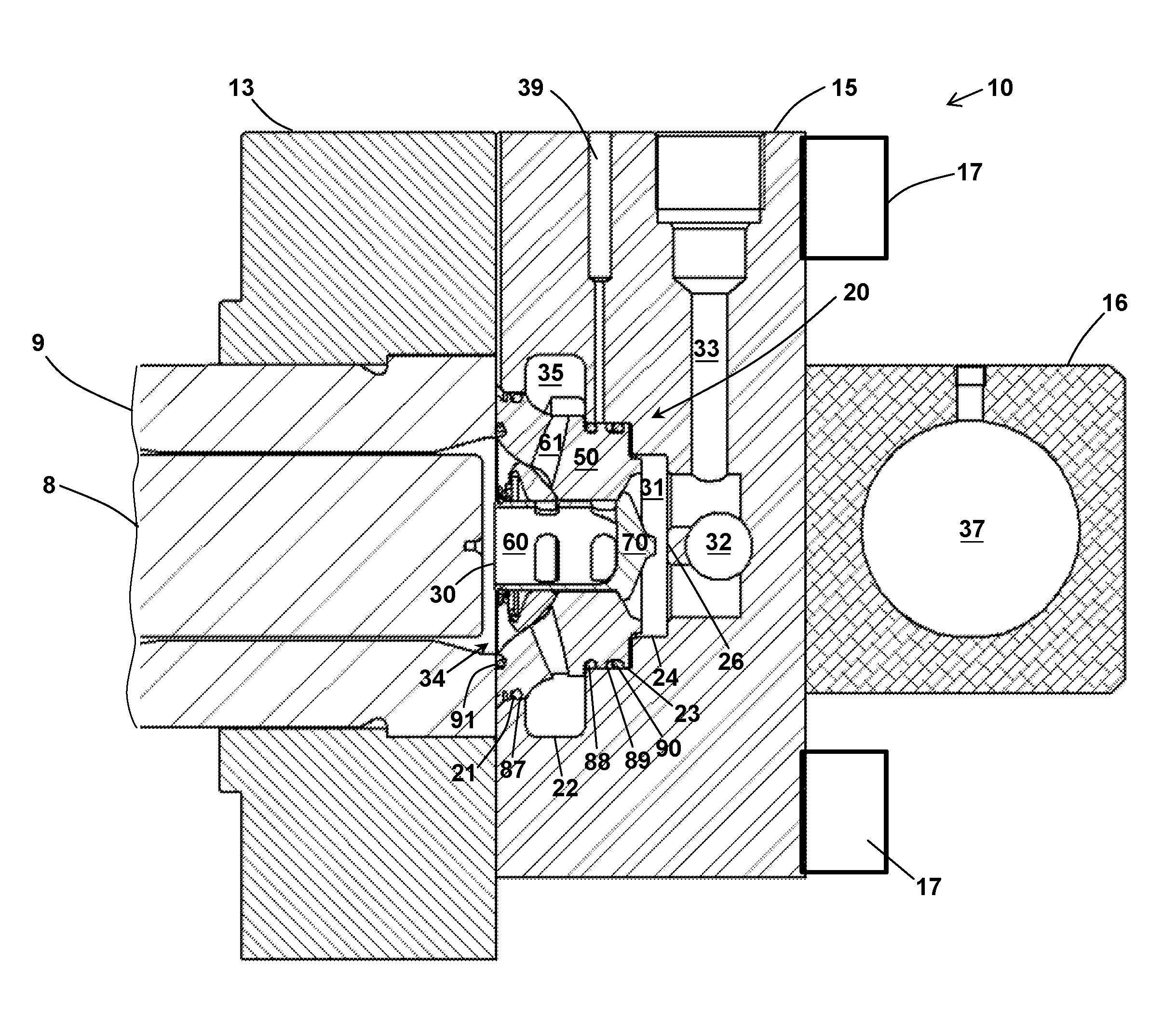
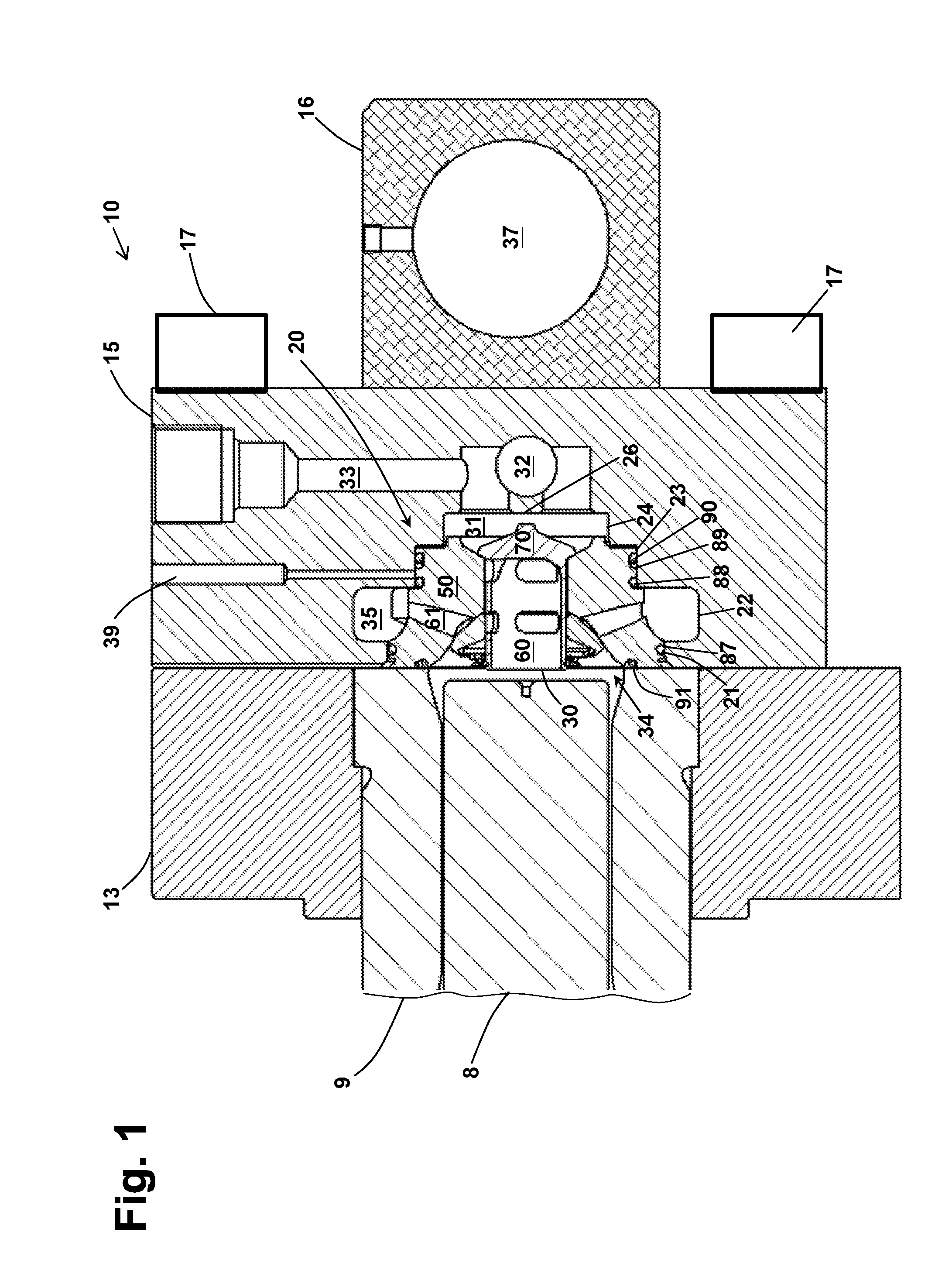
[0020]Referring to FIG. 1, a fluid end 10 of a high pressure reciprocating pump is shown as including a mounting block 13 for housing plunger box 9 and a manifold block 15 bolted to the pump fluid end 10 by fasteners 17. As shown, a plunger 8 reciprocally slides inside the plunger box 9 to create suction and compression strokes. In one aspect, the manifold block 15 has one or more pockets 18, each of which defines a plurality of differently sized, stepped bores 21, 22, 23, and 24 to accommodate the installation of variously sized...


PUM


Abstract

An improved manifold and valve cartridges suitable for high power (over 600 hp) reciprocating pumps for water blast or jet applications are disclosed. In one aspect, the disclosed valve cartridges are compact and mounted axially along a seat member that has a central bore in addition to suction and discharge seats. The seat member can also be provided a plurality of radially arranged bores for allowing suction flow to the pump. A spool valve assembly can be mounted through the seat member bore, and can include a valve spool, a spherical suction valve member, a compression spring, and compression-locked rings. The spool valve can include a closed flanged end that engages with the seat member discharge seat. In operation, the compression spring continuously pushes the spool valve closed flanged end against the discharge seat and pushes the suction valve member against the suction seat to retain a normally closed position.

Description

CROSS REFERENCE TO RELATED APPLICATION[0001]This application is a continuation of application Ser. No. 14 / 021,360, filed Sep. 9, 2013, which application is incorporated herein by reference in its entirety.TECHNICAL FIELD[0002]This invention relates to high power reciprocating pumps of the type used in high flow and high pressure water blast and jet applications, and more particularly to an improved manifold and valve cartridges for lower ownership cost.BACKGROUND[0003]Generally, an industrial reciprocating pump consists of three or five crankshaft-driven plungers to compress and eject fluid. A manifold is also often used to cap the open ends of the multiple plunger boxes and manage the flow during operation based on suction or discharge strokes. Traditionally, manifold pockets are provided in the manifold that communicate with the plunger chamber. Within the pockets, two individual check valves are provided to serve the suction and discharge functions, respectively. Such an arrangem...

Claims


Application Information

Patent Timeline
IPC IPC(8): F04B53/10F04B1/04
CPCF04B1/0452F04B53/10F04B39/10F04B39/1046F04B53/109Y10T137/6011
Inventor HUANG, XIAOLUN
Owner FEDERAL SIGNAL CORPORATION
Why Eureka
Try Eureka