Vacuum Pump

Active Publication Date: 2016-05-19
EDWARDS JAPAN
View PDF2 Cites 4 Cited by
  • Summary
  • Abstract
  • Description
  • Claims
  • Application Information

AI Technical Summary

Benefits of technology

[0030]In the invention described in claim 3, in addition to the effect of the invention described in claim 2, since the inflow suppressing wall suppresses the gas from flowing into the thread groove forward in the rotating direction of the rotor climbing over the exhaust side end portion and the gas in the thread groove is smoothly exhausted along the inflow suppressing wall formed in the taper shape of the ridge portion, it is possible to suppress the deposit of the gas product due to the retention of the gas on the exhaust side of the thread groove while suppressing an increase in an outlet pressure of the thread groove.
[0031]In the invention described in claim 4, in addition to the effect of the invention described in claim 2, since the inflow suppressing wall formed across the widened region suppresses the gas in the exhaust side outlet of the thread groove from flowing into the gas groove forward in the rotating direction of the rotor climbing over the exhaust side end portion of the ridge portion, it is possible to suppress the deposit of the gas product due to the retention of the gas in the exhaust side outlet of the thread groove.
[0032]In the invention described in claim 5, in addition to the effect of the invention described in claim 1, since the inflow suppressing wall suppresses the gas from flowing into the thread groove forward in the rotating direction of the rotor climbing over the exhaust side end portion of the ridge portion and an excessive decrease in a flow rate of the gas flowing in the thread groove involved in setting of the inflow suppressing wall is avoided, it is possible to suppress the

Problems solved by technology

Therefore, it is likely that a compression ratio

Method used


Image

  • Vacuum Pump
  • Vacuum Pump
  • Vacuum Pump

Examples


embodiments

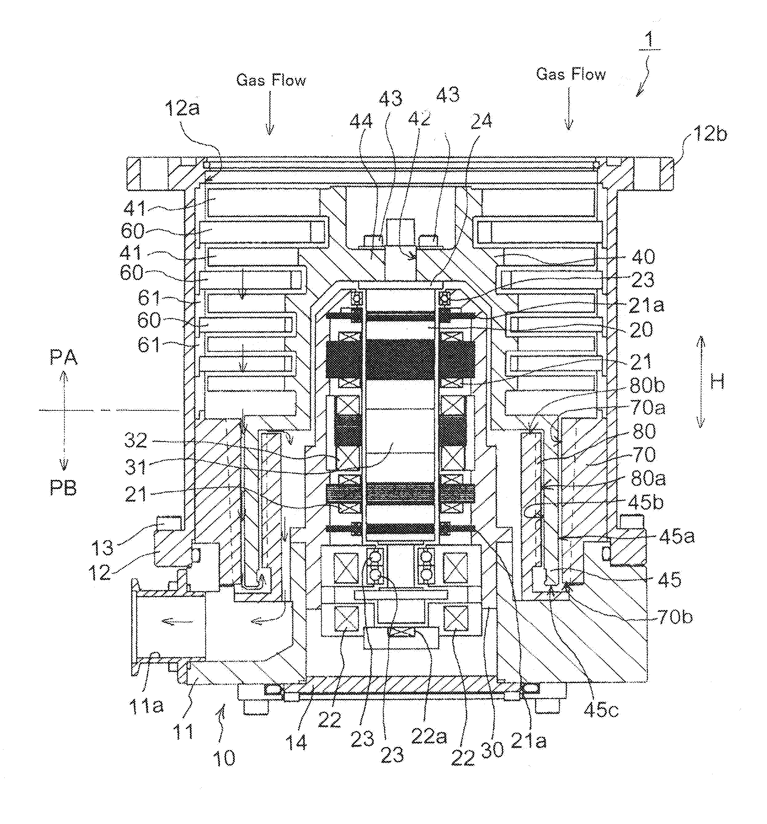
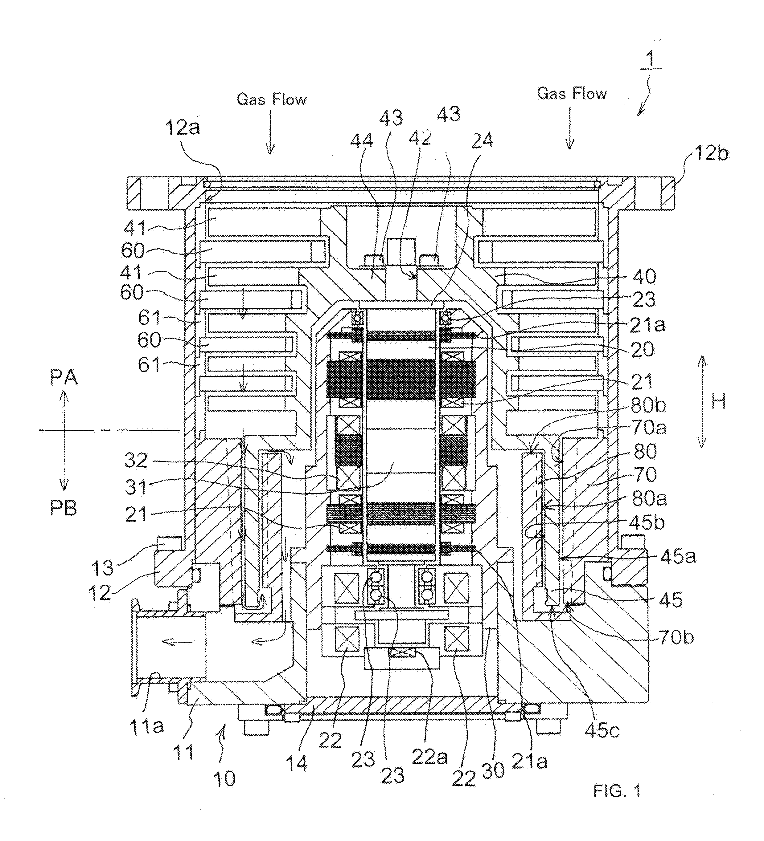
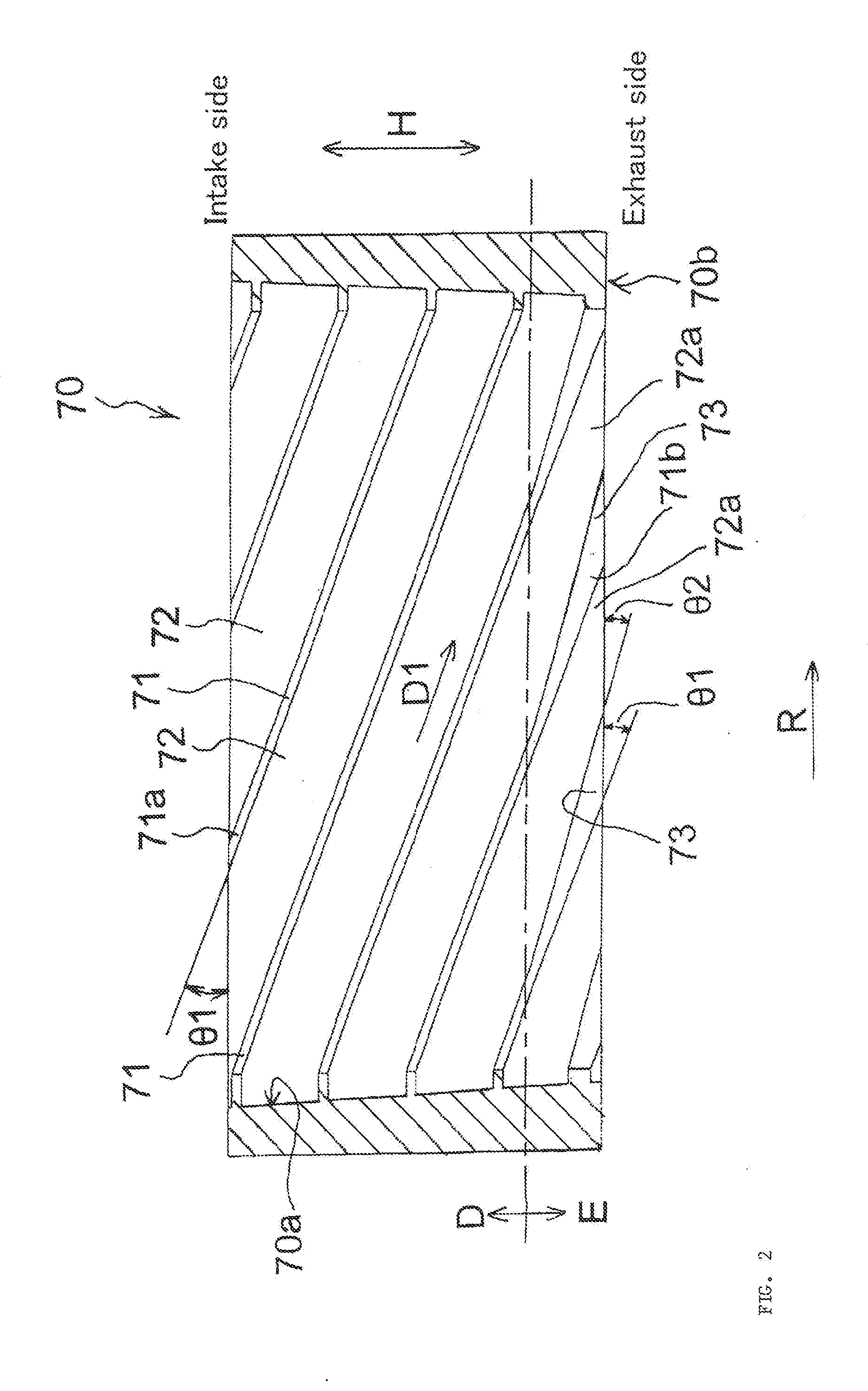
[0046]A vacuum pump according to a first embodiment of the present invention is explained with reference to FIGS. 1 to 3.

[0047]The vacuum pump 1 is a compound pump including a turbo molecular pump mechanism PA and a thread groove pump mechanism PB housed in a substantially cylindrical casing 10.

[0048]The vacuum pump 1 includes the substantially cylindrical casing 10, a rotor shaft 20 rotatably supported in the casing 10, a driving motor 30 that rotates the rotor shaft 20, a rotor 40 fixed to an upper part of the rotor shaft 20 and including rotary blades 41 provided in parallel concentrically with respect to the axis of the rotor shaft 20, and a stator column 50 that houses a part of the rotor shaft 20 and the driving motor 30.

[0049]The casing 10 is formed in a bottomed cylindrical shape. The casing 10 is configured by a base 11, in a lower part side of which a gas outlet port 11a is formed, and a cylinder portion 12, in an upper part of which a gas inlet port 12a is formed, the cyl...


PUM


Abstract

A vacuum pump is provided, which suppresses occurrence of a gas product in an exhaust side outlet of a thread groove and maintains pump performance over a long period. The vacuum pump includes inflow suppressing walls formed by widening greater an exhaust side end portion of ridge portions, extended along a gas exhaust direction on an outer circumferential surface of an inner circumference side stator, forward in a rotor rotating direction than an intake side end portion, the inflow suppressing walls suppressing retention of gas in exhaust side outlets of thread grooves engraved among the ridge portions.

Description

CROSS-REFERENCE TO RELATED APPLICATION[0001]This application is a Section 371 National Stage Application of International Application No. PCT / JP2014 / 065156, filed Jun. 6, 2014, which is incorporated by reference in its entirety and published as WO2015 / 001911 on Jan. 8, 2015 and which claims priority of Japanese Application No. 2013-141863, filed Jul. 5, 2013.FIELD OF THE INVENTION[0002]The present invention relates to a vacuum pump and, more particularly, to a vacuum pump usable in a pressure range from a medium vacuum to an ultra-high vacuum.BACKGROUND OF THE INVENTION[0003]When a semiconductor device such as a memory or an integrated circuit is manufactured, in order to avoid the influence due to dust and the like in the air, it is necessary to apply doping and etching to a high-purity semiconductor substrate (wafer) in a chamber in a high vacuum state. A vacuum pump such as a turbo molecular pump is used for exhaust in the chamber.[0004]As such a vacuum pump, there is known a vac...

Claims


Application Information

Patent Timeline
IPC IPC(8): F04D19/04F04D29/28F04D29/54F04D29/32F04D17/16F04D29/44
CPCF04D19/04F04D17/168F04D29/28F04D29/542F04D29/32F04D29/444F04D19/044F04D29/324F04D29/544F05D2240/122F05D2240/304F05D2250/70F05D2260/607
Inventor SAKAGUCHI, YOSHIYUKIMIWATA, TOORUMITSUHASHI, KEITA
Owner EDWARDS JAPAN
Why Eureka
Try Eureka