

Feed flow conditioner for particulate feed materials
a flow conditioner and feed material technology, applied in the direction of control devices for furnaces, combustion process, blast furnace components, etc., can solve the problems of affecting burner performance, poor oxygen efficiency, increased copper losses to slag, etc., to improve the combustion performance of flash smelting concentrate burners, reduce low-frequency fluctuations, and reduce the effect of spatial non-uniformity
- Summary
- Abstract
- Description
- Claims
- Application Information
AI Technical Summary
Benefits of technology
Problems solved by technology
Method used
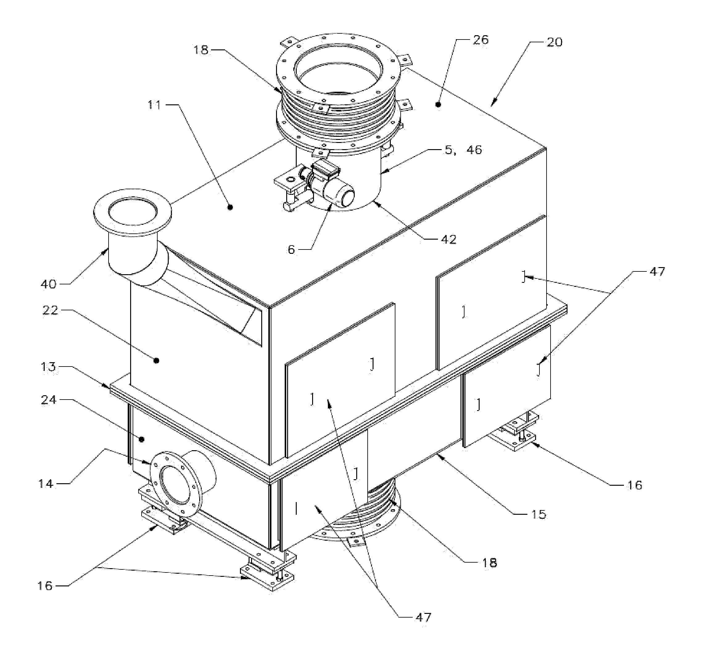
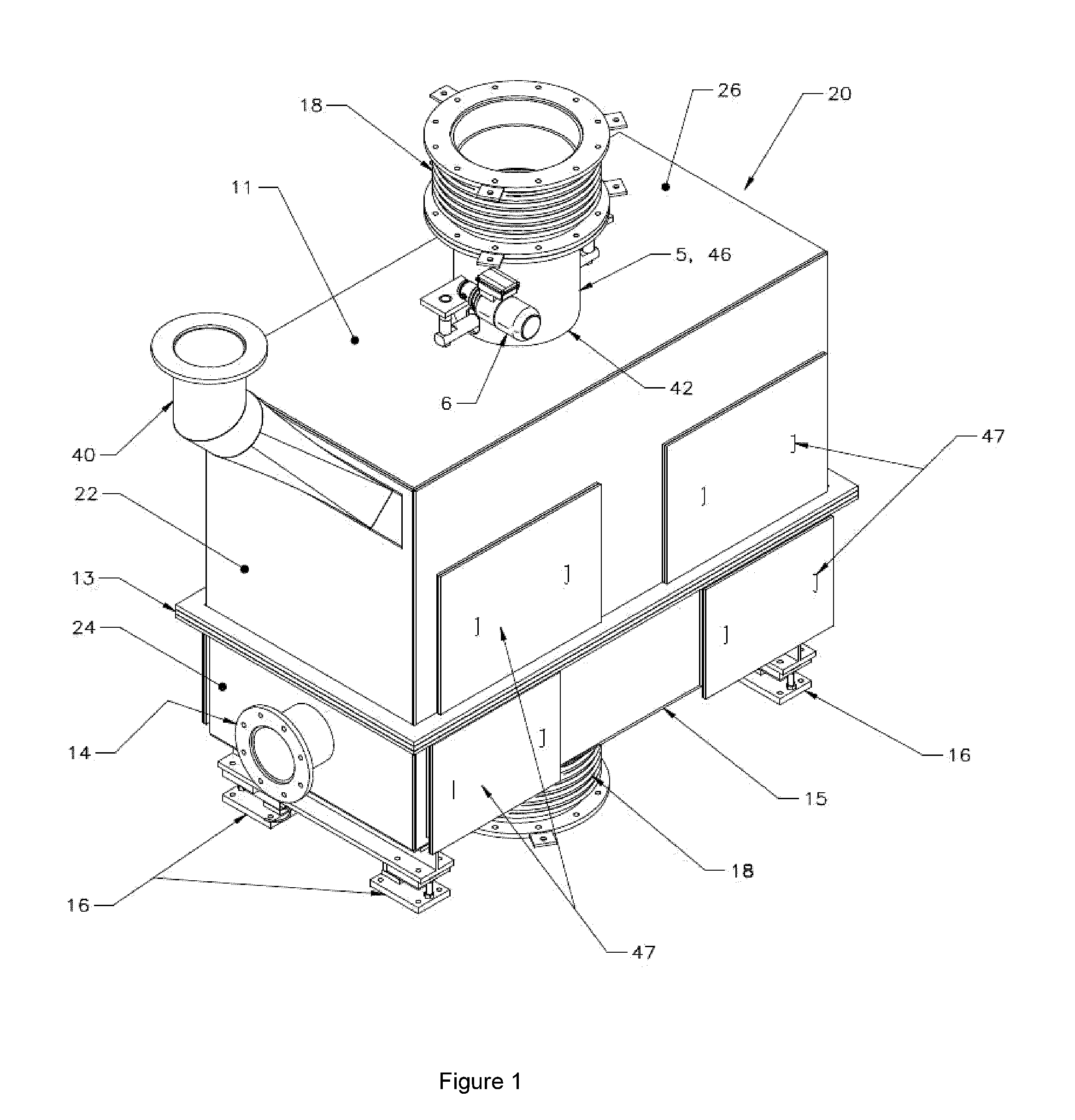
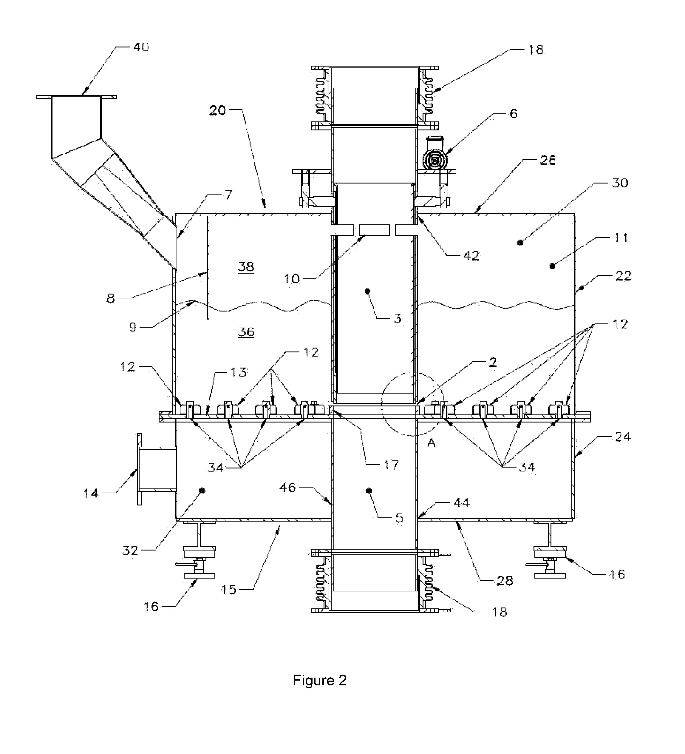
Image

Examples
example
[0108]A flash smelting furnace operating with a conventional feed system was simulated using an axisymmetric transient CFD model. Details of the modeling work can be found in a paper by Lamoureux et al. entitled “Impact of Concentrate Feed Temporal Fluctuations on a Copper Flash Smelting Process”, http: / / onlinelibrary.wiley.com / doi / 10.1002 / 9781118887998.ch52 / summary. Three transient conditions, with identical time-averaged feed rates, were modeled: (1) ideal, temporally uniform feed; (2) intermittent feed injected with a frequency of 1 Hz, with an 80% duty cycle; and (3) intermittent feed injected with a frequency of 5 Hz, with an 80% duty cycle. The latter two cases correspond to the feed frequencies of a conventional feed system, and the modeled natural frequency of a feed flow conditioner (as described herein), respectively. Performance of the burner was evaluated on the basis of oxygen efficiency. The reported values for the intermittent feed case are relative to the oxygen effi...
PUM
 Abstract
Description
Claims
Application Information