
Glenoid component installation procedure and tooling for shoulder arthroplasty

a technology for installing procedures and tooling, applied in the field of glenoid component installation procedures and tooling for shoulder arthroplasty, can solve the problems of severe loosen loosening of glenoid components, etc., and achieve the effect of reducing the chance of delamination of the prosthetic glenoid

Inactive Publication Date: 2016-05-26
THE GENERAL HOSPITAL CORP
View PDF8 Cites 24 Cited by
  • Summary
  • Abstract
  • Description
  • Claims
  • Application Information

AI Technical Summary

Benefits of technology

The present invention is a new technique for preparing the glenoid bone for a shoulder joint replacement. The technique involves reaming only the bearing part of the glenoid and leaving the cortex intact, which makes the glenoid component more stable and durable. The invention also uses an "inset" design, which preserves the periphery of the glenoid bone and only removes the inside of it, reducing edge-loading and failure. The preparation of the glenoid for the inset glenoid component is easier because only a smaller area of bone needs to be removed. Overall, the invention improves the stability and longevity of the shoulder joint replacement.

Problems solved by technology

Loosening of glenoid components can be a problem in total shoulder arthroplasty.
The consequence of glenoid component loosening can be severe, as a loosened glenoid component cannot always be replaced because of bone deficiencies.

Method used


Image

  • Glenoid component installation procedure and tooling for shoulder arthroplasty
  • Glenoid component installation procedure and tooling for shoulder arthroplasty
  • Glenoid component installation procedure and tooling for shoulder arthroplasty

Examples


Embodiment Construction

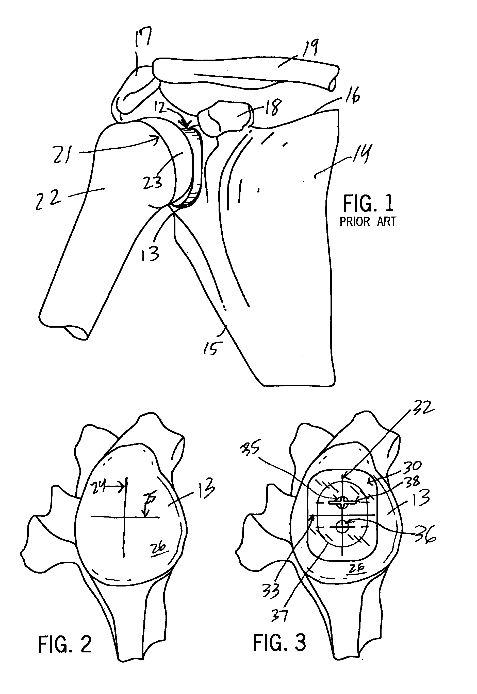
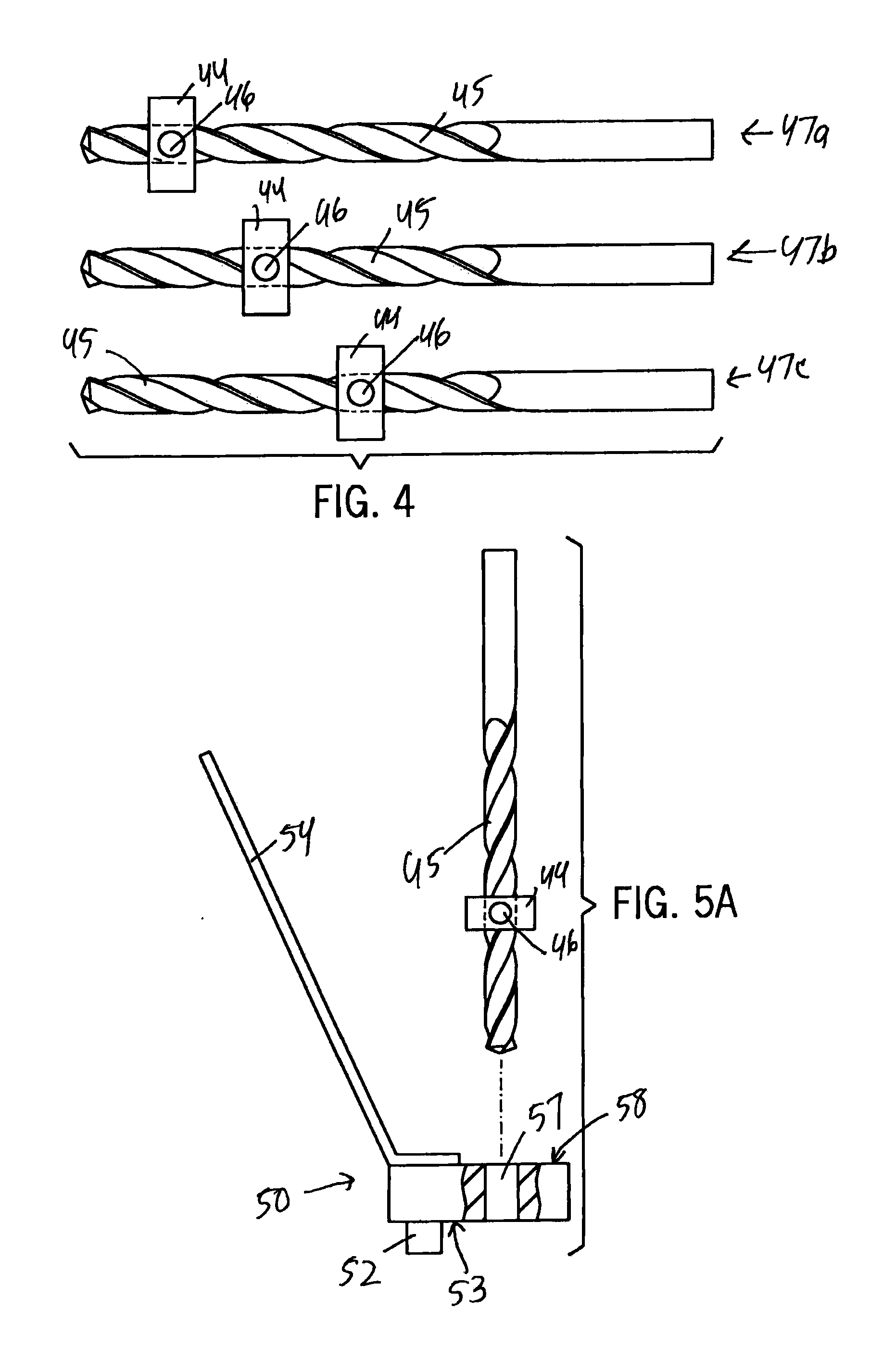
[0054]One non-limiting example version of a glenoid component installation procedure and tooling according to the invention is shown in FIGS. 2 to 12. The tooling and glenoid component can be provided as a kit for use with the method of the invention.

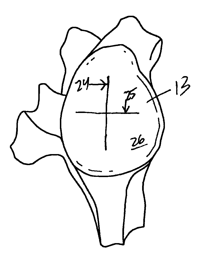
[0055]First, the glenoid surface is prepared. The surgeon marks an approximate vertical (superior to inferior) centerline 24 and a horizontal (anterior to posterior) centerline 25 on the surface 26 of the glenoid cavity 13 with a bone marking tool such as a cauterizer. See FIG. 2.

[0056]The appropriate size of glenoid component is selected for the application, and a corresponding size of transparent template 30 is placed over the surface 26 of the glenoid cavity 13 as shown in FIG. 3. A template vertical centerline 32 and a horizontal centerline 33 on the template 30 are then aligned with the centerlines 24, 25 drawn on the glenoid surface. The surface of the template 30 includes a first printed indicia 35 showing approximate location of...


PUM


Abstract

A method for implanting a glenoid component during shoulder arthroplasty is disclosed. In the method, a template is placed against a surface of a glenoid cavity of a scapula, and a bone marking tool is inserted through a cut-out guide in the template. The bone marking tool is used to create a bone mark on the surface of the glenoid cavity. A drill is aligned with the bone mark and a first pilot hole is drilled in the surface of the glenoid cavity. A locating pin of a first drill jig is placed in the first pilot hole, and a drill is inserted through a guide hole of the first drill jig to drill a second pilot hole in the surface of the glenoid cavity. Bone material is removed between the first pilot hole and the second pilot hole to create a slot in the surface of the glenoid cavity between the first pilot hole and the second pilot hole. A keel of a glenoid component is positioned in the slot, and the glenoid component is secured in the scapula. A kit is also provided for use with the method. The kit includes a glenoid component including a body having a first articulating surface and a second surface opposite the first articulating surface. The first articulating surface is dimensioned for engaging a head of a humerus or a humeral implant. The second surface is dimensioned for being secured to a scapula. The glenoid component further includes a keel extending away from the second surface. The kit also includes a transparent template having a cut-out guide dimensioned to receive a bone marking tool. The template preferably has an indication of a centerline of the template. The kit also includes a first drill jig having a locating pin and a guide hole dimensioned to receive a drill bit, and a cutting tool having a follower pin and a cutting surface.

Description

CROSS-REFERENCES TO RELATED APPLICATIONS[0001]This application claims priority from U.S. Patent Application No. 61 / 473,520 filed Apr. 8, 2011.STATEMENT REGARDING FEDERALLY SPONSORED RESEARCH[0002]Not Applicable.BACKGROUND OF THE INVENTION[0003]1. Field of the Invention[0004]This invention relates to a suite of custom tooling and a surgical technique for a process in which a prosthetic glenoid component is inset into the face of the existing glenoid bone.[0005]2. Description of the Related Art[0006]Total shoulder replacement is a well-accepted treatment option for patients with osteoarthritis of the shoulder (glenohumeral joint). This procedure involves replacement of both the humeral head and the glenoid. The humeral head can be replaced / resurfaced with either a stemmed implant which is secured, in part, in the canal of the humerus or a stemless implant which is secured with the humeral head itself. The glenoid is a pear-shaped bone which is part of the scapula. It is the “socket” o...

Claims


Application Information

Patent Timeline
Patent Type & Authority Applications(United States)
IPC IPC(8): A61F2/46A61B17/16A61F2/40
CPCA61F2/4612A61F2/4081A61B2090/034A61B2017/1778A61F2002/30884A61B17/1684A61B17/1778
Inventor HOLOVACS, THOMAS F.PANONE, AARON B.WOLLOWITZ, MICHAELSHANBHAG, ARUN
Owner THE GENERAL HOSPITAL CORP
Learn More