Rechargeable battery with internal current limiter and interrupter

a rechargeable battery and current interrupter technology, applied in the direction of batteries, cell components, safety/protection circuits, etc., can solve the problems of two electrodes, a risk of short circuit, and a risk of overcharging, so as to achieve safe charging voltage, high energy density, and safe operating temperature range

Active Publication Date: 2016-05-26
AMERICAN LITHIUM ENERGY CORP
View PDF0 Cites 25 Cited by
  • Summary
  • Abstract
  • Description
  • Claims
  • Application Information

AI Technical Summary

Benefits of technology

[0012]The improvement for this first aspect of the disclosure is employable for slowing the rate of internal discharge resulting from the short circuit, for slowing the production of joule heat therefrom, and for reducing the risk of thermal runaway.
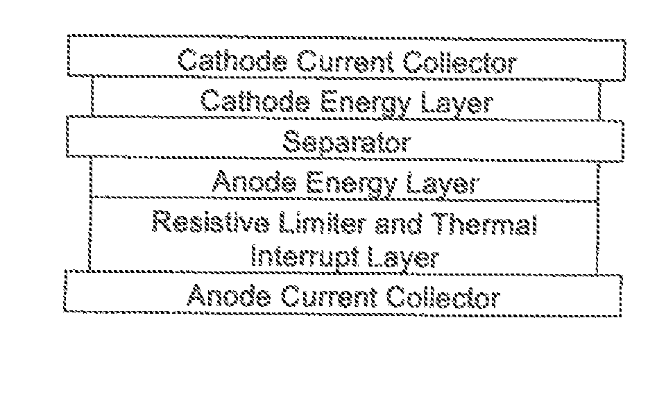
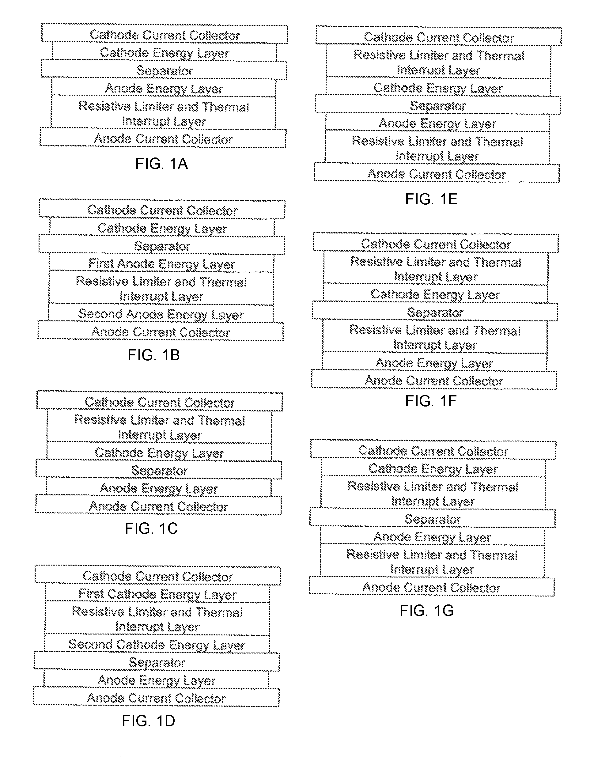
[0014]The current limiter 6 forms an electrical coupling between one of the electrodes (12 or 14) and its corresponding current collector 4. The current limiter 6 has a resistivity for resistively impeding current therethrough and, in the event the separator 2 forms the short circuit, for diverting current from the electrode current collector 4 to which it is coupled, and for reducing the rate of the internal discharge between the two electrodes (12 and 14).
[0021]In this first aspect of the disclosure, the current limiter 6 and the current interrupter 8, in combination, diminishes the risk of thermal runaway resulting from separator short circuit, electrode overcharge, and electrode overheating.
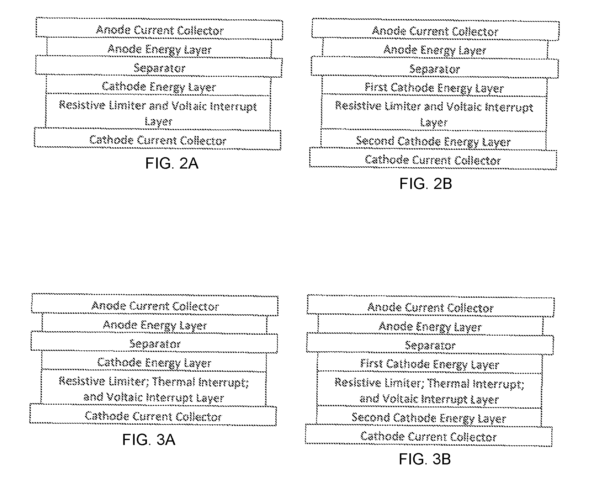
[0035]The thermally activatable current interrupter 8 is layered by lamination between one of the current collectors 4 and one of the electrodes (12 or 14). The thermally activatable current interrupter 8, when unactivated, electrically couples the current collector 4 to the electrode (12 or 14) with which it is layered, said current interrupter 8. When activated, the thermally activatable current interrupter 8 delaminates from the current collector 4 for forming a nonconductive gap for electrically decoupling the current collector 4 from the electrode (12 or 14) with which it had been layered. The electrical decoupling serves to slow the rate of internal discharge between the two electrodes (12 and 14) in the event of separator failure.
[0036]The voltage activatable current interrupter 8 is layered by lamination between one of the current collectors 4 and one of the electrodes (12 or 14). The voltage activatable current interrupter 8, when unactivated, electrically couples the current collector 4 to the electrode (12 or 14) with which it is layered. The current interrupter 8, when activated, delaminates from the current collector 4 by forming a nonconductive gap for electrically decoupling the current collector 4 from the electrode (12 or 14) with which it had been layered. The resultant electrical decoupling serves to slow the rate of internal discharge between the two electrodes (12 and 14) in the event of separator failure. In this second aspect of the disclosure, activation of either the thermally activated current interrupter 8 or the voltage activated current interrupter 8 in the event of separator failure, slows the generation joule heat for diminishing the potential danger.
[0037]A second aspect of the disclosure is directed to a process for avoiding thermal runaway within a high energy density rechargeable battery undergoing internal discharge due to separator failure. The process comprises the step of delaminating an electrode (12 or 14) within the battery from its current collector 4 by generating a gas from a heat sensitive gas generating material within an interrupt layer interposed between the electrode (12 or 14) and current collector 4. The delamination electrically decouples the electrode (12 or 14) from its current collector 4 for slowing the rate of internal discharge.

Problems solved by technology

The separator 2 is subject to a risk of forming a short circuit.
The two electrodes (12 and 14) are subject to a risk of overcharge above the safe charging voltage and the formation of the short circuit therefrom.
The two electrodes (12 and 14) are subject to a risk of thermal runaway above the safe operating temperature range.

Method used


Image

  • Rechargeable battery with internal current limiter and interrupter
  • Rechargeable battery with internal current limiter and interrupter
  • Rechargeable battery with internal current limiter and interrupter

Examples


example 1

Preparation of Baseline Electrodes, Positive and Negative Electrodes, and the Completed Cell #1 for the Evaluation in the Resistance Measurement, Discharge Capability Tests at 50° C., Impact Test, and Cycle Life Test

[0246]A) Preparation of POS1 A as an Example of the Positive Electrode Preparation.

[0247]i) Dissolve PVDF (21.6 g) into NMP (250 g); ii) Add carbon black (18 g) and mix for 15 minutes at 6500 rpm; iii) Add LiNi0.5Mn0.3CO0.2O2 (NMC) (560.4 g) to the slurry from Step ii and mix for 30 minutes at 6500 rpm to form a flowable slurry; iv) Some NMP may be added for the viscosity adjustment; v) Coat this slurry onto 15 □ Coat this slurry onto 15 the viscosity adjustment; e slurry; pability tests at 50eted Cell ° C. and the second heat zone to about 130° C. to evaporate off the NMP. The final dried solid loading is about 15.55 mg / cm2. The positive layer was then compressed to a thickness of about 117 μm. The electrode made here is called as zero voltage against graphite electrode...

example 2

Preparation of CaCO3 Based Gas Generator and Resistive Layer, Positive and Negative Electrodes, and the Completed Cell #3 for the Evaluation in the Resistance Measurement, Discharge Capability Tests at 50° C., Impact Test, Over Charge, and Cycle Life Test

[0253]A) Positive POS3B as an Example of a Gas Generator and Resistive Layer (1st Layer) Preparation.

[0254]i) Dissolve Torlon®4000TF (0.8 g) into NMP (10 g); ii) Dissolve PVDF (4.8 g) into NMP (˜70 g); iii) Mix solution prepared in Step i and ii, and then add carbon black (0.32 g) and mix for 10 minutes at 6500 rpm; iv) Add nano CaCO3 powder (34.08 g) to the solution from Step iii and mix for 20 minutes at 6500 rpm to form a flowable slurry; v) Coat this slurry onto 15□ Coat this slurry onto 15 6500 rpm to form a flowable slurry; 6500 rpm; sts at 50 completed Cell #° C. and the second heat zone to about 165° C. to evaporate off the NMP. The final dried solid loading is about 1 mg / cm2.

[0255]B) Preparation of POS3 A as an Example of t...

example 3

[0262]Preparation of 50% Al2O3 and 50% CaCO3 based gas generator and resistive layer, positive and negative electrodes, and the completed Cell #4 for the evaluation in the resistance measurement, discharge capability tests at 50° C., impact test, over charge and cycle life tests:

[0263]A) Positive POS4B as an Example of a Gas Generator and Resistive Layer (1st Layer) Preparation.

[0264]i) Dissolve Torlon®4000TF (0.8 g) into NMP (10 g); ii) Dissolve PVDF (4.8 g) into NMP (˜70 g); iii) Mix solution prepared in Step i and ii, and then add carbon black (0.32 g) and mix for 10 minutes at 6500 rpm; iv) Add nano CaCO3 powder (17.04 g) and Al2O3 powder (17.04 g) to the solution from Step iii and mix for 20 minutes at 6500 rpm to form a flowable slurry; v) Coat this slurry onto 15□ Coat this slurry onto 15 6500 rpm to form a flowable slurry; 6500 rpm; sts at 50 completed Cell #° C. and the second heat zone to about 165° C. to evaporate off the NMP. The final dried solid loading is about 1 mg / c...


PUM

PropertyMeasurementUnit
energy densityaaaaaaaaaa
resistivityaaaaaaaaaa
charging voltageaaaaaaaaaa

Abstract

A high energy density rechargeable (HEDR) battery employs a combined current limiter / current interrupter to prevent thermal runaway in the event of internal discharge or other disruption of the separator. The combined current limiter / current interrupter is interior to the battery.

Description

BACKGROUND[0001]1. Technical Field[0002]This disclosure relates to an internal current limiter or current interrupter used to protect a battery in the event of an internal short circuit or overcharge leads to thermal runaway. In particular, it relates to a high energy density rechargeable (HEDR) battery with improved safety.[0003]2. Background[0004]There is a need for rechargeable battery systems with enhanced safety which have a high energy density and hence are capable of storing and delivering large amounts of electrical energy per unit volume and / or weight. Such stable high energy battery systems have significant utility in a number of applications including military equipment, communication equipment, and robotics.[0005]An example of a high energy density rechargeable (HEDR) battery commonly in use is the lithium-ion battery.[0006]A lithium-ion battery is a rechargeable battery wherein lithium ions move from the negative electrode to the positive electrode during discharge and ...

Claims


Application Information

Patent Timeline
Patent Type & Authority Applications(United States)
IPC IPC(8): H01M2/34H01M10/0525H02J7/00H01M50/574
CPCH01M2/34H02J7/0031H01M2200/10H01M10/0525H02J2007/0037H01M2/348H01M10/052H01M10/4235H01M2200/20Y02E60/10H01M50/581H01M50/578H01M50/574H01M10/425H01M2010/4271
Inventor FAN, JIANGWU, DENGGUO
Owner AMERICAN LITHIUM ENERGY CORP
Why Eureka
Try Eureka