

Circular polarizing filter and application thereof
a filter and circular technology, applied in the field of circular polarizing filters, can solve the problem of not being able to achieve completely circular polarized light, and achieve the effect of improving the sensitivity of the sensor system
- Summary
- Abstract
- Description
- Claims
- Application Information
AI Technical Summary
Benefits of technology
Problems solved by technology
Method used
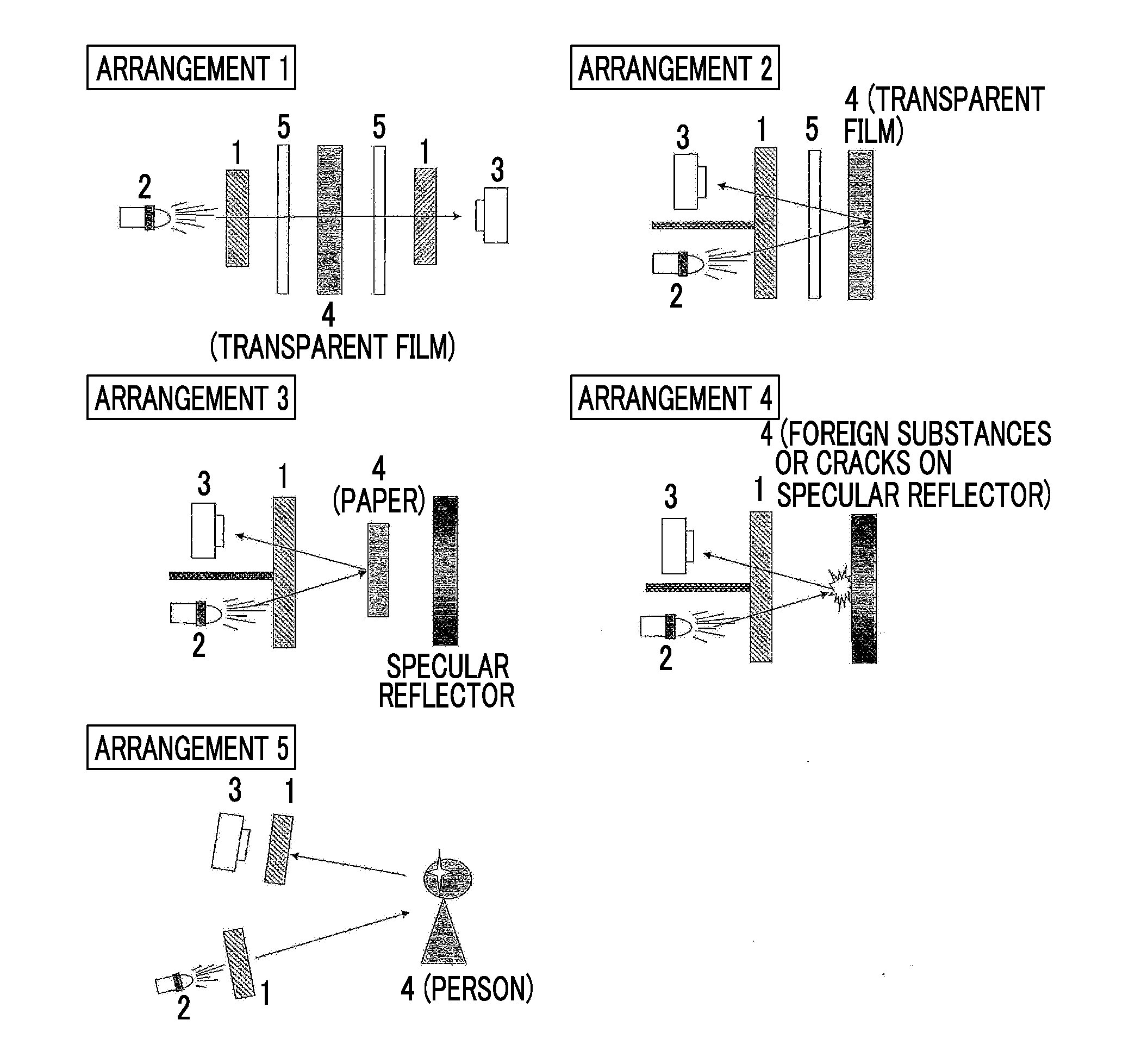
Image

Examples
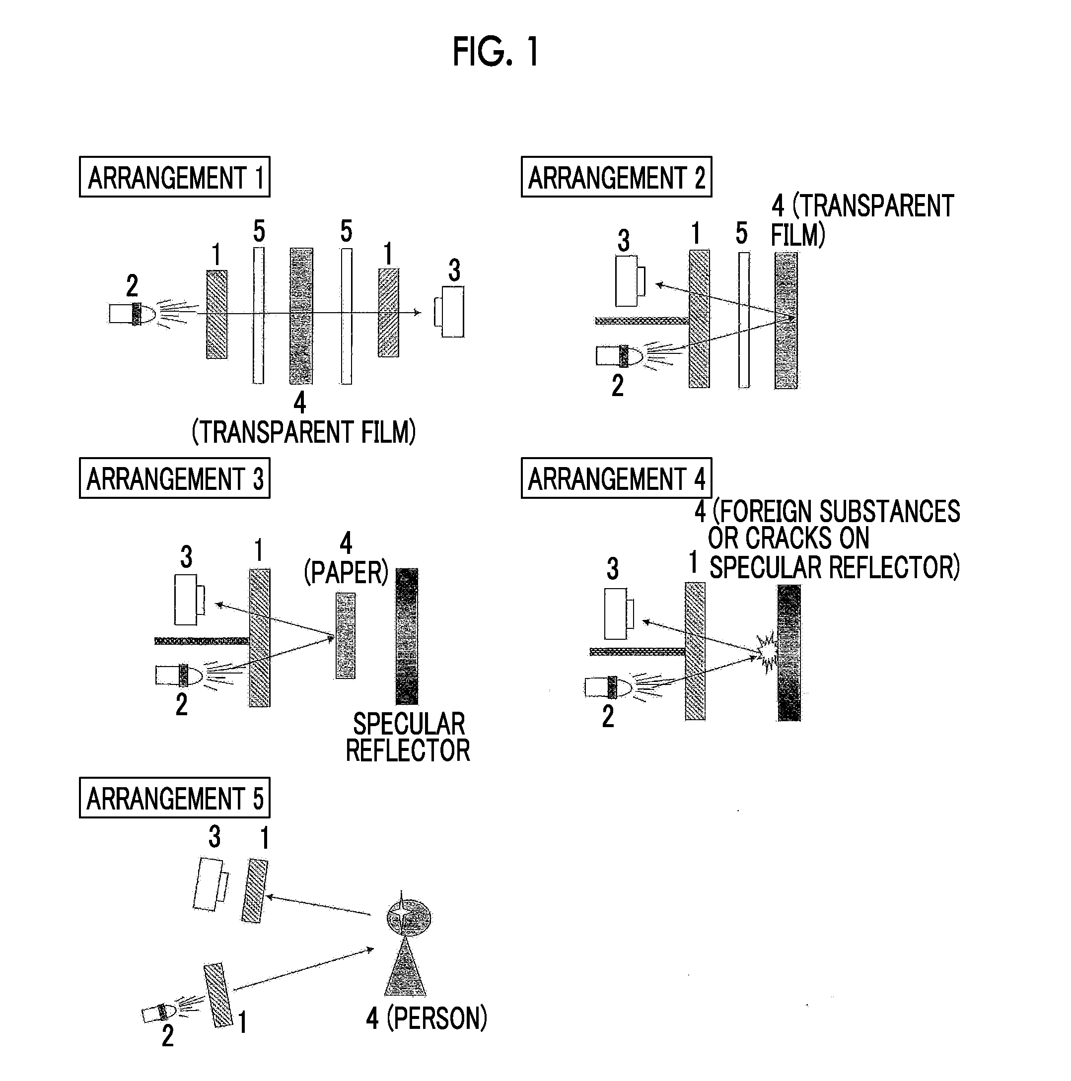
example 1
[0237]A polyimide varnish Sunever 130 manufactured by Nissan Chemical Industries, Ltd. was applied with a thickness of 0.2 μm on a glass substrate, and then heated for 1 hour at 250° C. to form a substrate with an attached alignment film. On this surface, a coating liquid A-1 shown in Table 1 was applied by using a wire bar at room temperature such that a thickness of the dried film after drying was 4.4 μm. After being dried for 30 seconds at room temperature, the coating layer was heated for 2 minutes under an atmosphere at 85° C., and then UV-irradiated for 6 seconds to 12 seconds using a D-bulb (lamp 90 mW / cm) manufactured by Heraeus K.K. Noblelight Division with an output of 60% at 30° C. to obtain a circular polarizing filter of Example 1.
examples 2 to 4
[0238]Circular polarizing filters of Examples 2 to 4 were obtained in the same manner as in Example 1, except that the thickness of the dried film after drying was 2.7 μm, 1.8 μm, and 1.0 μm, respectively, by adjusting the wire bar number and the solvent amount.
example 5
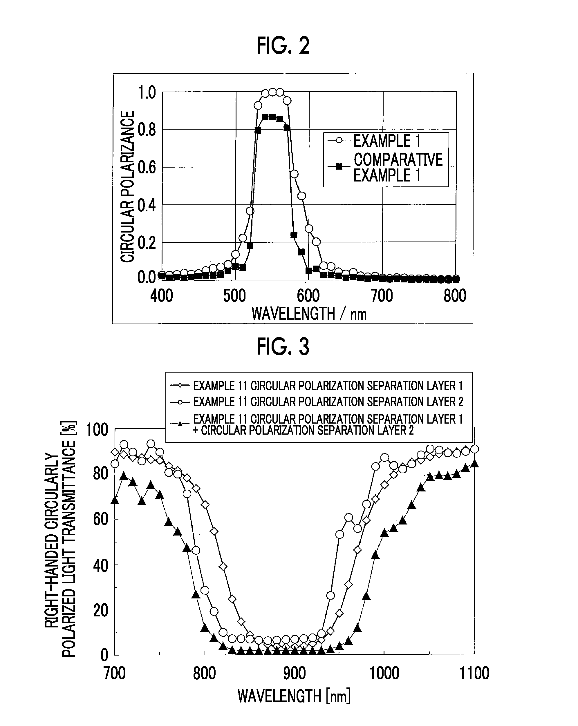
[0239]To the glass substrate with an attached alignment film produced in the same manner as in Example 1, a coating liquid A-2 shown in Table 1 was applied by using a wire bar at room temperature such that a thickness of the dried film after drying was 5.0 μm. After being dried for 30 seconds at room temperature, the coating layer was heated for 2 minutes under an atmosphere at 85° C., and then UV-irradiated for 6 seconds to 12 seconds using a D-bulb (lamp 90 mW / cm) manufactured by Heraeus K.K. Noblelight Division with an output of 60% at 30° C. to fix a cholesteric liquid crystal layer. Thus, a circularly-polarized light separating layer was obtained.
[0240]To a film IR80 manufactured by Fujifilm Corporation as a visible light absorption layer, a UV-curable adhesive Exp. U12034-6 manufactured by DIC Corporation was applied by using a wire bar at room temperature such that the thickness of the dried film after drying was 5 μm. This coating surface and the surface on the liquid crysta...
PUM
 Abstract
Description
Claims
Application Information