
Self-expanding cannula

Active Publication Date: 2016-06-09
UNIV OF MARYLAND BALTIMORE
View PDF9 Cites 6 Cited by
  • Summary
  • Abstract
  • Description
  • Claims
  • Application Information

AI Technical Summary

Benefits of technology

The patent describes a new type of cannula (a device used to drain fluids from a patient's body) that has a self-expanding wire frame that helps keep the patient's blood vessels open and prevents them from collapsing. This cannula has two lumens (channels for fluid drainage and blood infusion) and can be used for percutaneous cannulation (a minimally invasive procedure to insert a cannula into a patient's blood vessel) for both Veno-Pa and Veno-RV modes of therapy. Additionally, the patent describes a double lumen cannula that can be used for both drainage and blood infusion simultaneously. This new cannula system helps improve patient outcomes and minimize the risk of complications during therapy.

Problems solved by technology

Blood flow in a person's body, and particularly the oxygen carried by that person's blood as it courses through their body, is adversely affected by heart failure and lung disease, both of which are pervasive killers.
Heart failure occurs when the heart cannot pump sufficient blood to meet the needs of the body.
The condition creates a major burden on health care providers and is expensive to treat.
Despite advances in medical care, the prognosis for patients with heart failure remains poor, especially when in advanced stages.
Of course, heart transplantation is limited by a limited supply of donor organs.
While use of VAD's is increasing, it nonetheless remains limited due to the need for major operative intervention.
If a patient's lungs do not function properly (e.g., due to COPD or ARDS), the oxygenation of blood is not sufficient.
Because of the major invasive nature of the procedures for implanting those devices, only a limited population of patients receives these device-based therapies.
The major problems of available cannulae for ECMO (as described in U.S. Pat. No. 7,473,239 to Wang et al., the specification of which is incorporated herein by reference in its entirety) include: (1) multiple cannulation and insertion of cannulae with larger diameters causing extra trauma to patients; (2) blood recirculation leads to insufficient extracorporeal oxygenation; and (3) the placement of the drainage lumen causes insufficient venous blood drainage.
Similarly, cannulation technologies used in VAD's share at least the problem of causing extra trauma to patients.

Method used


Image

  • Self-expanding cannula
  • Self-expanding cannula
  • Self-expanding cannula

Examples


Embodiment Construction

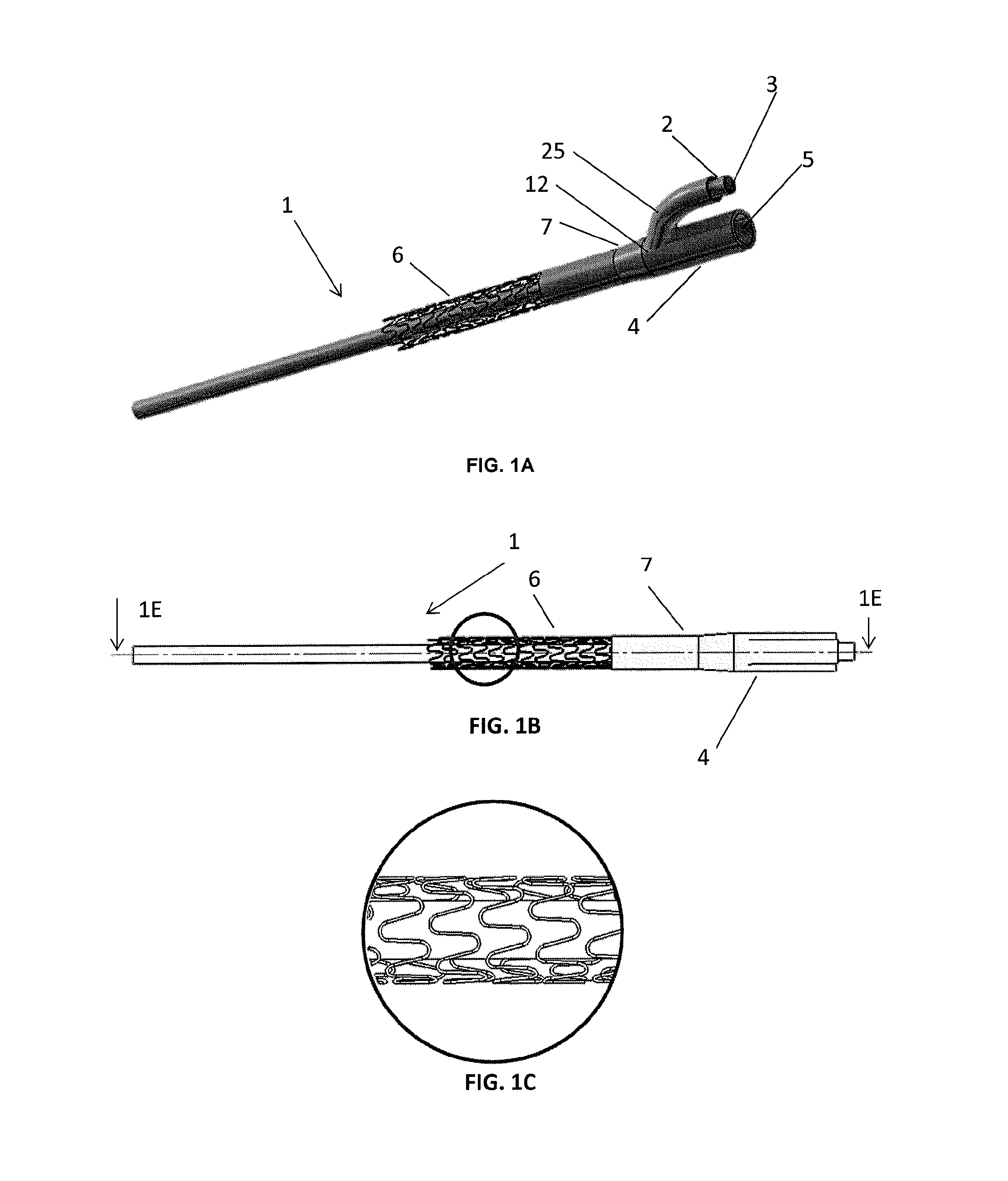
[0010]Disclosed herein is a novel, self-expanding cannula, systems using such cannulae, and methods of their use. The cannulae may comprise single lumen cannula (“SLC”) configurations and double lumen cannula (“DLC”) configurations. The cannula includes at least a first cannula and a self-expanding wire frame attached to the first cannula. The self-expanding wire frame may, for example, be temperature-responsive to expand from a compressed state (providing a reduced cannula diameter as it is moved through a patient's body to the site at which it is to be deployed) to an expanded state (which increases the diameter of the cannula to the diameter intended for its normal use) in response to warming of the wire frame, such as from the patient's own body temperature. Alternatively, the wire frame may have sufficient flexibility so as to allow it to be radially compressed (such as by inserting the wire mesh and cannula to which it is attached into a tearable sheath for initial insertion i...


PUM


Abstract

Disclosed is a self-expanding cannula, systems using such cannulae, and methods of their use. The cannulae may comprise single lumen cannula (SLC) configurations and double lumen cannula (DLC) configurations, and include at least a first cannula and a self-expanding wire frame attached to the first cannula. Self-expanding wire frame is automatically expandable from a compressed state (providing a reduced cannula diameter as it is moved through a patients body to the site at which it is to be deployed) to an expanded state (which increases the diameter of the cannula to the diameter intended for its normal use). The expanded wire frame provides radial support to prevent a drainage canal (whether a patients blood vessel or a portion of the system inserted into the patients blood vessel) from collapsing as fluid is drained from the patient.

Description

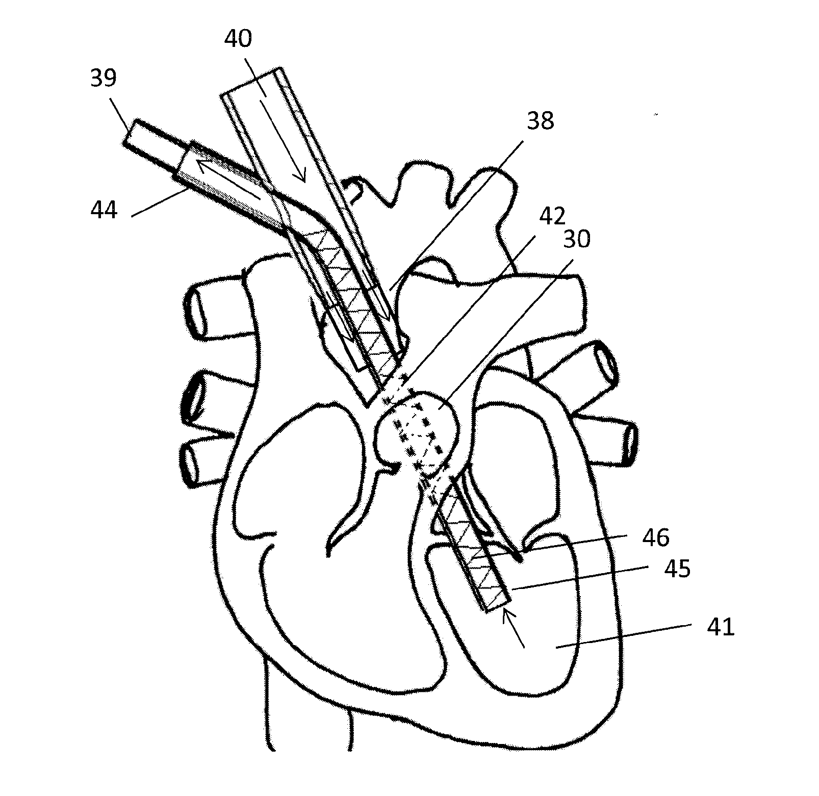
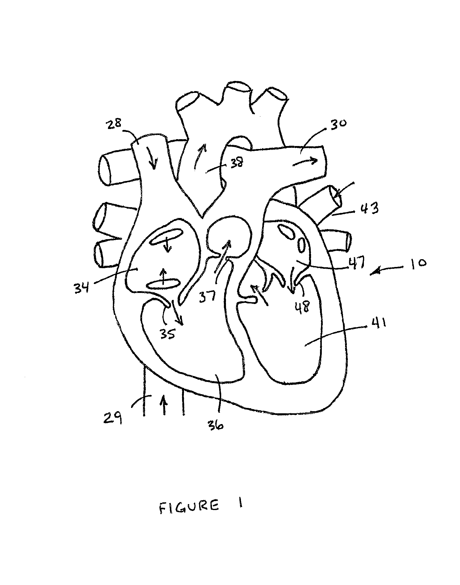
CROSS-REFERENCE TO RELATED APPLICATIONS[0001]This application is based upon and claims priority from co-pending U.S. Provisional Patent Application Ser. No. 61 / 847,638 entitled “Self-Expanding Cannula,” filed with the United States Patent and Trademark Office on Jul. 18, 2013, by the inventor herein, the specification of which is incorporated herein by reference in its entirety.FIELD OF THE INVENTION[0002]The present invention relates generally to medical devices, and more particularly to cannulas, systems using cannulas and methods for their use.BACKGROUND OF THE PRIOR ART[0003]As preliminary background, blood circulation in a person's heart is described here to provide a better understanding of certain aspects of embodiments of the invention as set forth herein. In that regard, FIG. 1 is a diagram of a heart 10 and the circulatory flow within the heart. Blood travels to the heart from the upper part of the body through the superior vena cava (“SVC”) 28, and from the lower part of ...

Claims


Application Information

Patent Timeline
IPC IPC(8): A61M25/00A61M1/36
CPCA61M25/003A61M1/3659A61M2205/0266A61M2025/0035A61M2025/0039A61M2025/0031A61M25/04A61M25/005A61M2025/0024A61M2025/0059
Inventor WU, ZHONGJUNGRIFFITH, BARTLEY P.DING, JUN
Owner UNIV OF MARYLAND BALTIMORE
Learn More