Hydraulic suspension damper

a damper and suspension technology, applied in the field of hydraulic dampers, can solve the problems of twin-tube dampers, low internal pressure of working liquid filling the damper, and inability to use external tubes, etc., and achieve the effects of improving the damper assembly process, simple stamping process, and cost saving

Active Publication Date: 2016-06-16
BEIJINGWEST INDUSTRIES
View PDF9 Cites 3 Cited by
  • Summary
  • Abstract
  • Description
  • Claims
  • Application Information

AI Technical Summary

Benefits of technology

[0010]Preferably the damper of the present invention is a mono-tube damper. This enables for achieving simplicity of damper construction, although the additional chamber assembly may obviously also be used as an additional tuning add-on in a twin-tube damper, for example to provide additional tuning options.
[0011]Preferably said additional chamber assembly comprises a uniform body, preferably screwed to the end of the piston rod. This provides a cost efficient method of manufacturing the chamber assembly in a simple stamping process.
[0012]Preferably said additional chamber assembly is a separate subassembly of the damper independently assembled and filled with a pressurized gas. This further improves damper assembly process.

Problems solved by technology

Twin-tube dampers also require relatively low pressure of the pressurised gas what results in relatively low internal pressure of the working liquid filling the damper, inducing relatively low friction force between a piston rod and a rod guide seal.
Furthermore, the external tube is not used to guide the slidable piston assembly.
Nonetheless, twin-tube dampers also have some disadvantages due to their complex structure, such as inter alia the necessity to provide a base valve assembly and a rod guide of a construction enabling for support of the external tube.
However, other problems arise.
Moreover, a certain dead zone exists at the end of the gas chamber where possible deformations of the main tube (which in this case is also an external tube) might lead to jamming of the slidable partition or otherwise limiting its sliding movement.
Finally mono-tube dampers often provide significantly limited tuning capabilities as compared to twin-tube dampers.
Yet another common disadvantage of both the above-mentioned damper types is a necessity to fill the gas chamber with a pressurised gas which process depends on the process of filing the damper with a working liquid.

Method used


Image

  • Hydraulic suspension damper
  • Hydraulic suspension damper
  • Hydraulic suspension damper

Examples


Embodiment Construction

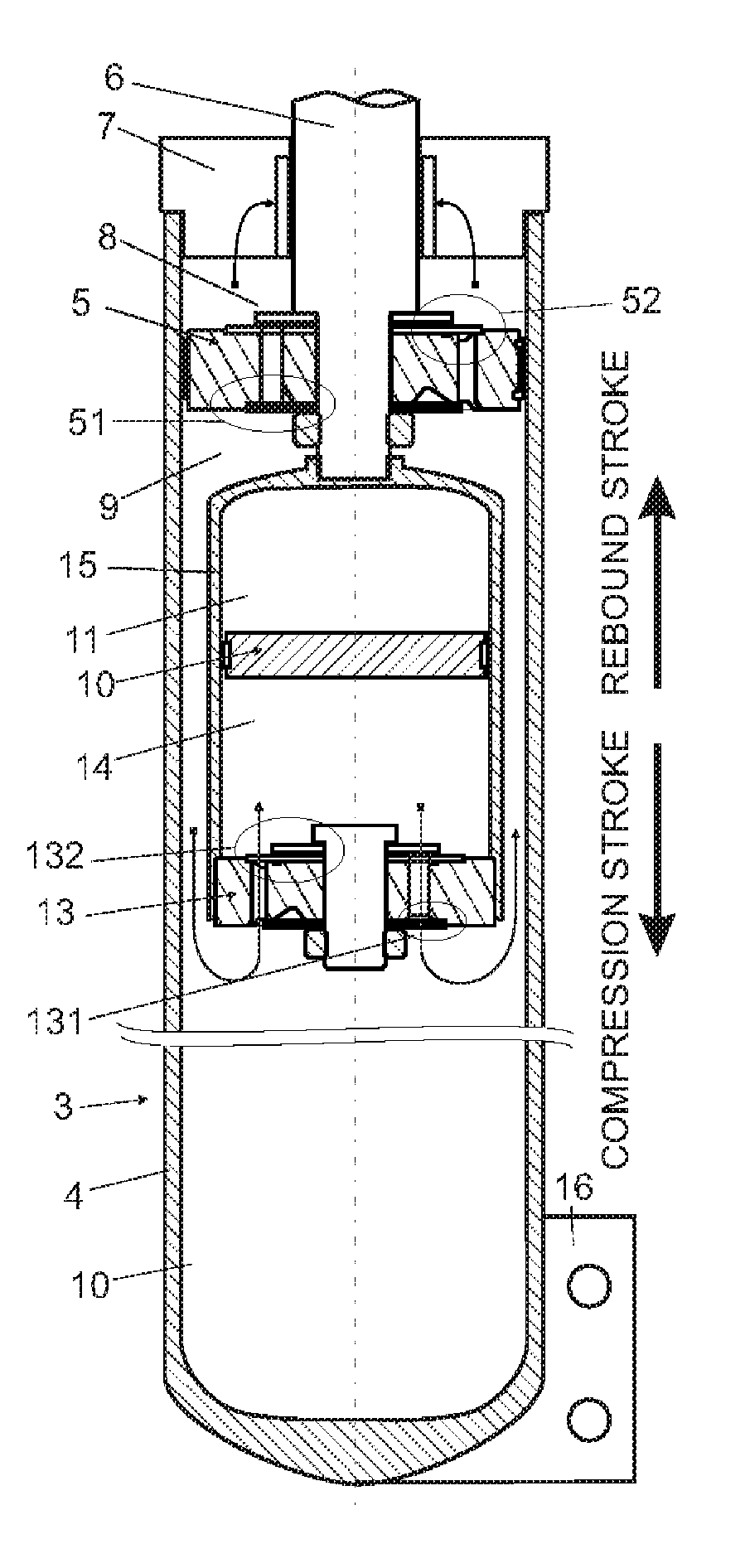
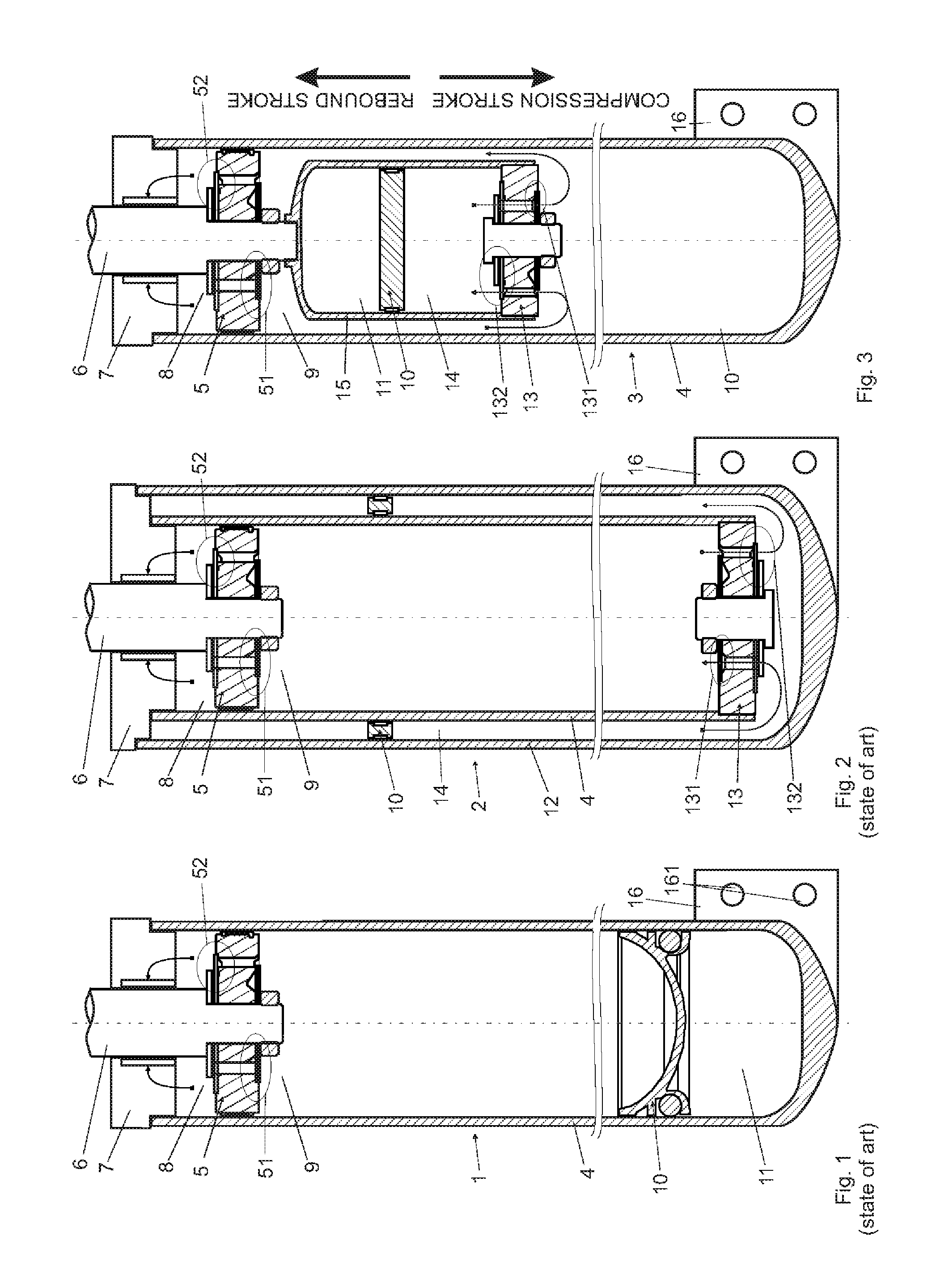
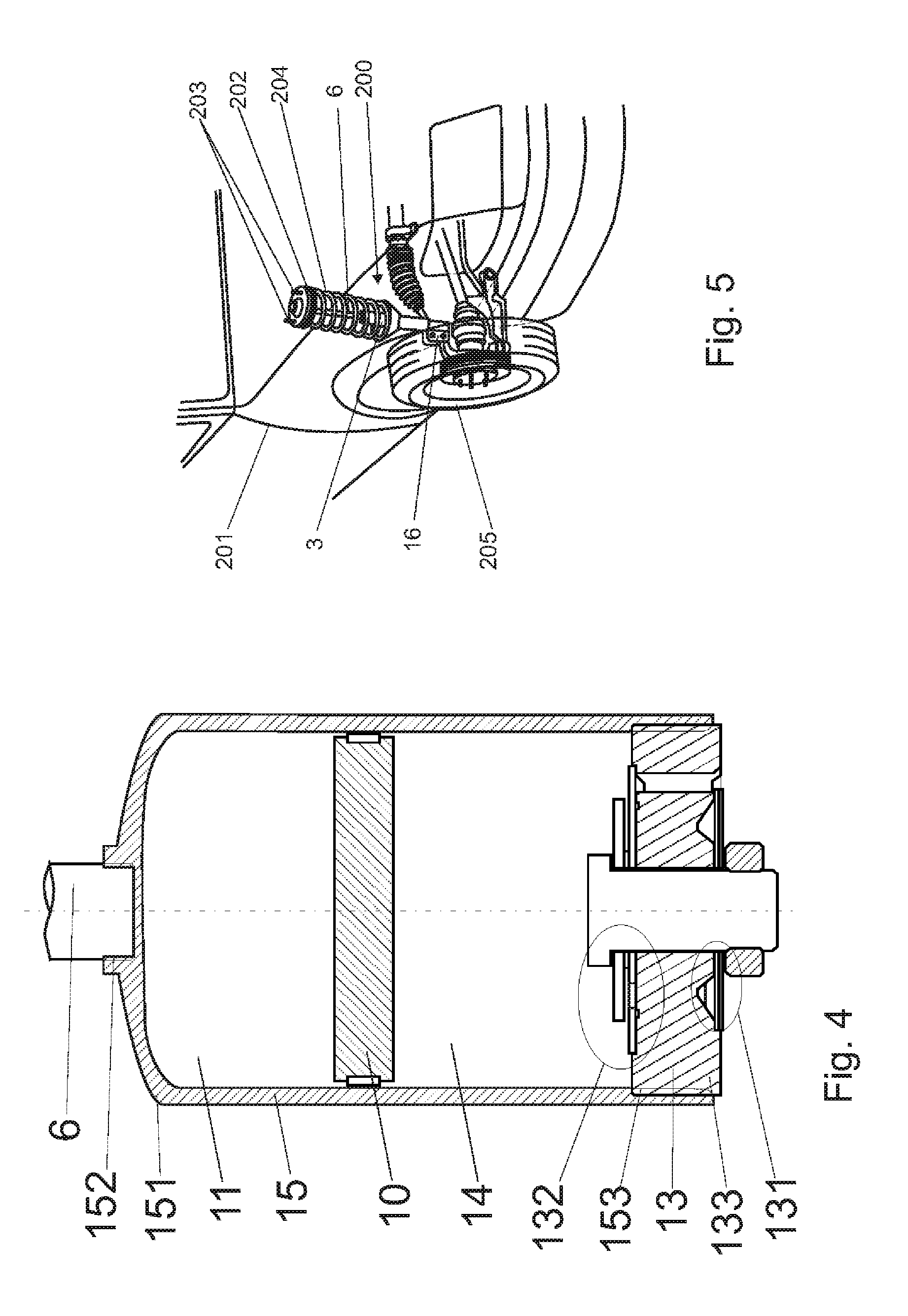
[0019]A hydraulic damper 1 shown in part in FIG. 1 is an example of a mono-tube hydraulic damper that may be employed in a vehicle suspension 200 presented in FIG. 5. It is shown almost fully extended in its position close to the end of the rebound stroke and comprises main cylinder tube 4 inside of which a piston assembly 5 is slidably disposed. The piston assembly 5 is attached to a piston rod 6 led outside the main tube 4 through a sealed piston rod guide 7 located at the end of the tube. The other end (not shown) of the piston rod 6 may be connected to the top mount 202 of the vehicle suspension 200. The opposite end of the tube 4 is provided with an attachment means 16, in a form of a bracket with two mounting holes 161, apt to fix the damper 1 to the steering knuckle or a swing arm supporting the vehicle wheel 205.

[0020]Arched arrow lines running from the rebound chamber 8 to the sealing of the piston rod guide 7 schematically symbolize a friction force between the rod guide 6...


PUM


Abstract

A hydraulic damper (3) includes a tube (4), a piston assembly (5) disposed slidably inside the tube (4), and an additional valve assembly (13). A compression chamber (9) is defined between the piston assembly (5) and the additional valve assembly (13). An additional compensation chamber (14) is defined between the additional valve assembly (13) and one side of a slideable partition (10). A gas chamber (11) is defined at the other side of the slidable partition (10). The damper includes an additional chamber assembly (15) to retain all the advantages of a twin-tube damper while providing the single construction offered by a mono-tube damper. One end of the additional chamber assembly (15) is attached to the slidable piston chamber (5) or to said piston rod (6) at the compression side thereof and the other end of said additional chamber assembly (15) is terminated with the additional valve assembly (13).

Description

FIELD OF THE INVENTION[0001]The invention relates to a hydraulic damper, in particular a motor vehicle suspension damper, comprising: a tube; a piston assembly disposed slidably inside the tube and attached to a piston rod led outside the tube through a sealed piston rod guide located at the end of the tube, wherein a rebound chamber filled with working liquid is defined between said piston rod guide and said piston assembly; an additional valve assembly, wherein a compression chamber filled with working liquid is defined between said piston assembly and said additional valve assembly; a slidable partition, wherein an additional compensation chamber filled with working liquid is defined between said additional valve assembly and one side of said slidable partition; a gas chamber filled with pressurised gas and defined at the other side of said slidable partition; wherein said piston assembly is provided with rebound valve and compression valve to control the flow of working liquid p...

Claims


Application Information

Patent Timeline
Patent Type & Authority Applications(United States)
IPC IPC(8): B60G13/08F16F9/06
CPCB60G13/08B60G2206/41B60G2202/24F16F9/061F16F9/064F16F9/067F16F2230/32
Inventor SLUSARCZYK, PAWELGOLDASZ, JANUSZ
Owner BEIJINGWEST INDUSTRIES
Why Eureka
Try Eureka