Systems and methods for providing optimized taxiing path operation for an aircraft

a taxiing path and optimization system technology, applied in the field of aircraft taxiing systems, can solve the problems of insufficient accuracy and data/time consumption of applications, large workloads of flight crews, slow and cumbersome manual process of entering sequences, etc., and achieve the effect of small memory space and easy embedding in different sequences

Active Publication Date: 2016-06-16
AIRBUS OPERATIONS (SAS)
View PDF1 Cites 23 Cited by
  • Summary
  • Abstract
  • Description
  • Claims
  • Application Information

AI Technical Summary

Benefits of technology

[0012]Advantages are achieved by the present taxiing path optimization system which includes an improved Airport Graph Database (AGDB) for storing specific information relating to geographic and geometric relationships between an aircraft and its surrounding objects in a two or three dimensional coordinate system. The present taxiing path optimization system further inc

Problems solved by technology

As a result, the workloads of the flight crews become significant and convoluted during airport surface operations.
Today, certain conventional applications are provided for an effective taxing operation, but these applications are not accurate enough and are data/time consuming.
This manual process of entering the sequence is slow and cumbersome because the clearance needs to be continuous (i.e., each clearance element must be connected to a successive one).
Thus, the flow graph of the airport includes unnecessary geometrical descriptions of the airport, causing memory space waste, longer computation time, and redundant complexity for generating the taxi route.
Further, because this type of flow graph does not include an explicit connectivity of each edge, the associated application must determine to which set of edges a given edge is connected, thereby causing additional computation time.
Typically, this type of flow graph only includes taxiways and runways, and does not have parking apron and deicing areas, making it impossible to compute the taxi route from or to a gate or a parking stand.
Another disadvantage of the conventional applica

Method used


Image

  • Systems and methods for providing optimized taxiing path operation for an aircraft
  • Systems and methods for providing optimized taxiing path operation for an aircraft
  • Systems and methods for providing optimized taxiing path operation for an aircraft

Examples


Embodiment Construction

[0038]Preferred embodiments of the present disclosure are described below by way of example only, with reference to the accompanying drawings. Further, the following description is merely exemplary in nature and is in no way intended to limit the disclosure, its application, or uses. As used herein, the term “module” or “unit” may refer to, be part of, or include an Application Specific Integrated Circuit (ASIC), an electronic circuit, a processor (shared, dedicated, or group) and / or memory (shared, dedicated, or group) that executes one or more software or firmware programs, a combinational logic circuit, and / or other suitable components that provide the described functionality. Thus, while this disclosure includes particular examples and arrangements of the modules, the scope of the present system should not be so limited since other modifications will become apparent to the skilled practitioner.

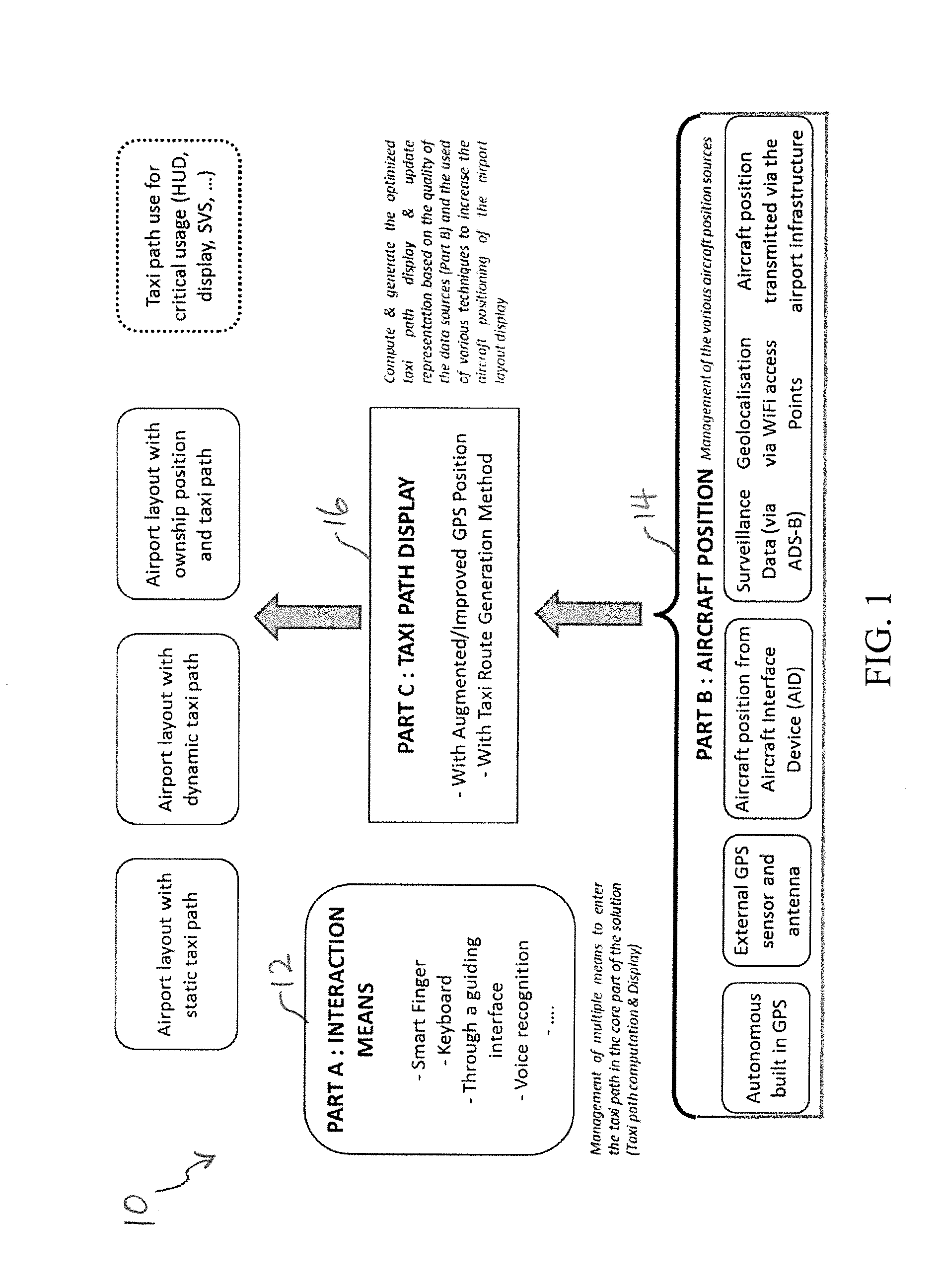
[0039]Referring now to FIG. 1, the present taxiing path optimization system is general...


PUM


Abstract

A taxiing path optimization system is provided for computing a taxi path of an aircraft using available taxi routes of a corresponding airport. An interaction means management unit manages interactions between a user and the taxiing path optimization system using an interactive device for inputting a taxi clearance. An aircraft positioning management unit manages positional information of the corresponding airport and aircraft received from a plurality of sources for augmenting an aircraft position by consolidating the aircraft position with the positional information in a complementary fashion. A taxi path display unit displays the taxi path based on the inputted taxi clearance and the augmented aircraft position, wherein the taxi path is automatically computed based on aircraft characteristics or airport capabilities.

Description

FIELD OF THE DISCLOSURE[0001]The present disclosure generally relates to aircraft taxiing systems, and in particular relates to a taxiing path optimization system for an aircraft using positioning data collected from various sources.BACKGROUND OF THE INVENTION[0002]To assist in navigation in an airport, a process of taxiing typically includes receiving a clearance from an air traffic controller (ATC), checking the received clearance, entering the received clearance into a navigation system for displaying the clearance on a map, and building a taxi route from a current position to a destination position, for example, on a runway or at a parking gate.[0003]In preparation for the taxiing, flight crews perform several tasks. The crews determine an accurate position of the aircraft by observing its external surroundings and / or a map. Then, the crews find and monitor a taxiing path based on the ATC clearance while monitoring an outside events and movements for preventing collision with ot...

Claims


Application Information

Patent Timeline
IPC IPC(8): G08G5/06G01C21/28G08G5/00G01C21/36
CPCG08G5/065G01C21/3667G08G5/0013G01C21/3626G08G5/0021G01C21/28B64F1/002G01C21/20G01C21/3453
Inventor DEPARE, PIERRESCACCHI, PIERRELOUISE, PASCALEBOUNAIX, FRANCOISSTANISLAWIAK, THOMAS
Owner AIRBUS OPERATIONS (SAS)
Why Eureka
Try Eureka