
Dual-chamber syringe and associated connecting systems

Inactive Publication Date: 2016-06-23
THORNE CONSULTING FOR INT PROPERTY LLC
View PDF10 Cites 12 Cited by
  • Summary
  • Abstract
  • Description
  • Claims
  • Application Information

AI Technical Summary

Benefits of technology

This patent describes a dual-chamber syringe system that prevents reflux (the reuse of liquid from a previous injection) using two approaches. The first approach involves a stem that can be reset to close the valve and conduit pathway from the liquid only zone, preventing further reflux. The rear plunger, which displaces the valve stem, is designed to be unresilient and have distally disposed geometry to inhibit reflux resulting from flow stoppage by collision between the plunger valve stem and rear plunger rod. The second approach involves an inflexible interface between a shoulder on the plunger rod stem and a proximal edge of the associated syringe. This hard stop prevents plunger motion that would cause reflux, even when the gas in the proximal chamber is still pressurized. Relief of the pressure of the gas provides a continued gradual downstream liquid flow rather than reflux. This patent also discusses the advantages of a dual-chamber syringe over a single chamber syringe, such as reduced requirements for interconnecting steps and likelihood of contamination being prominent considerations. It also mentions a female liquid source vessel that improves safety and efficacy of the dual-chamber syringe system. In addition, the patent describes the use of tamper-evident indicators to assure the integrity of the dual-chamber system. Overall, this patent aims to provide improvements in safety, efficiency, and reliability of the dual-chamber syringe system.

Problems solved by technology

It is well known in medical syringe art that canting of a plunger results in misalignment between plunger edge and indicia lines making measurement less accurate.
However, an unattached fluid driven plunder, such as the chamber separating plunger in a dual-chamber syringe, must be canting free for other reasons.
However, a ring is a separate part which adds to the overall cost of the dual-chamber syringe in which it is employed.
In addition to resisting canting, such rear support also precludes departure of outer cylindrical portions of the associated plunger from the inner surface of the barrel which would otherwise result in liquid communicating within the plunger to barrel interface, a condition which is highly undesirable.

Method used


Image

  • Dual-chamber syringe and associated connecting systems
  • Dual-chamber syringe and associated connecting systems
  • Dual-chamber syringe and associated connecting systems

Examples


Embodiment Construction

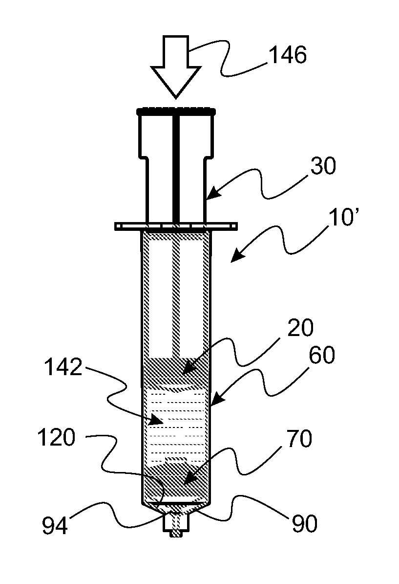
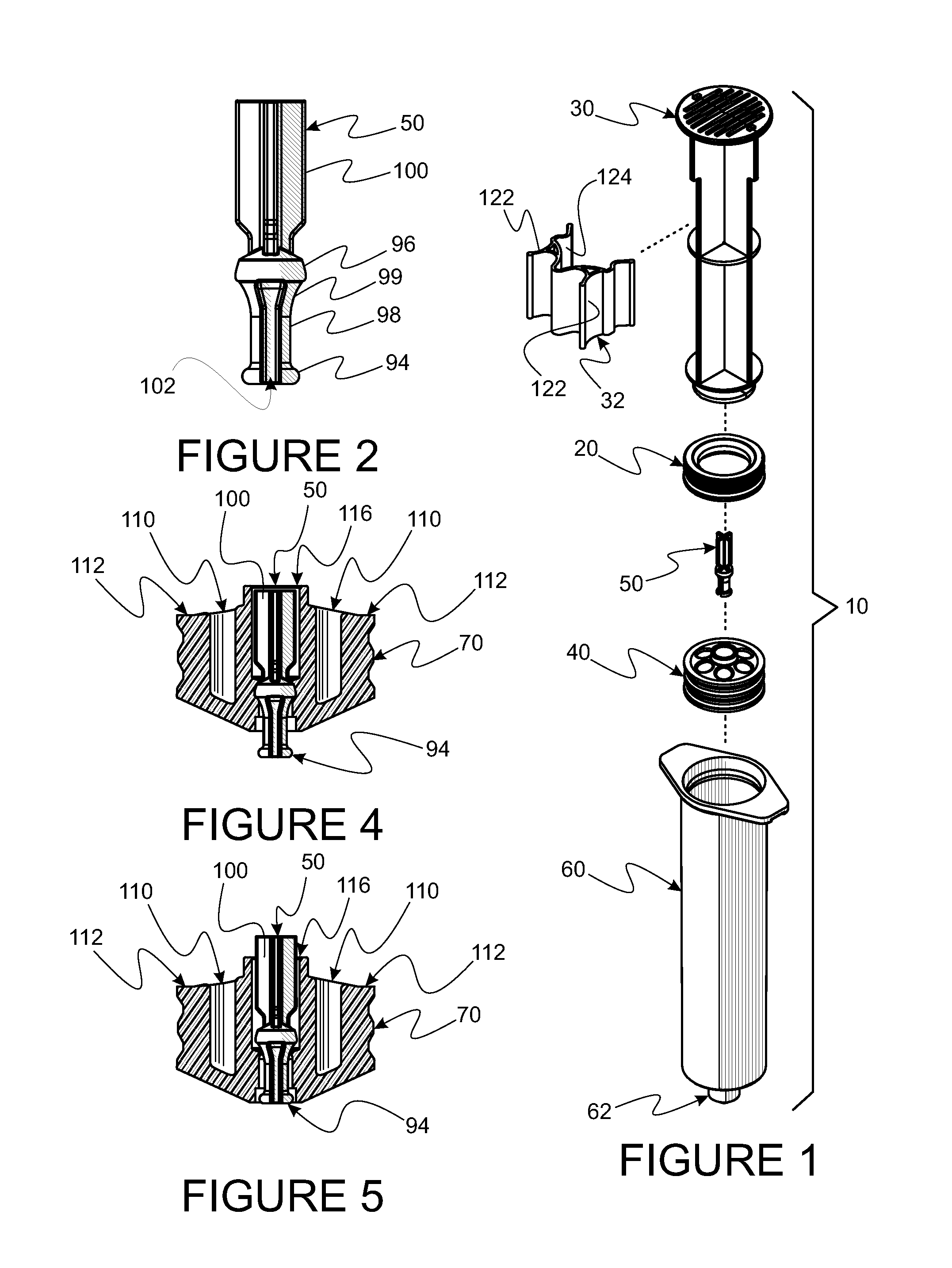
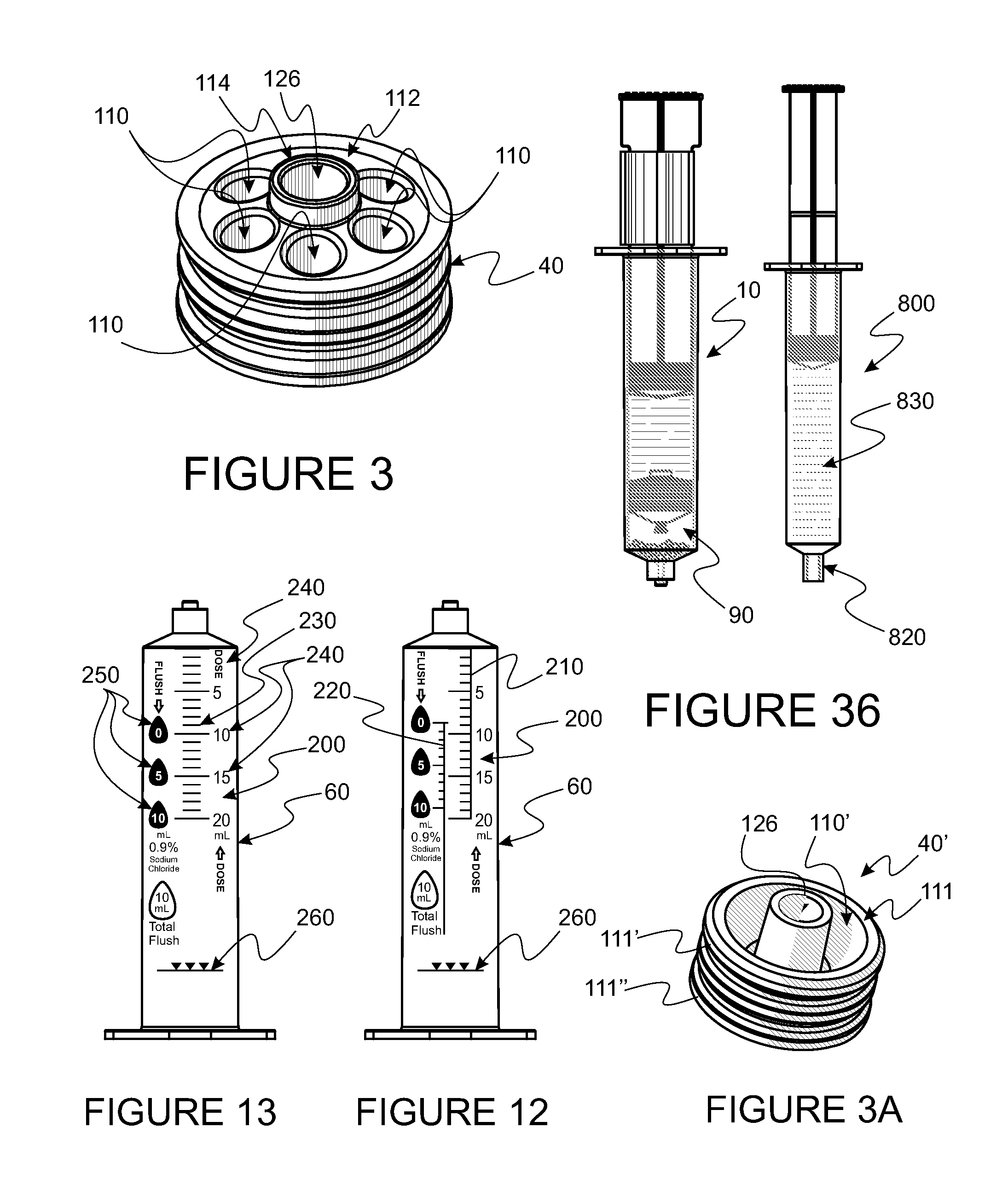
[0125]While the instant inventions disclosed herein are applicable to a wide variety of dual-chamber syringe applications and a number of tapered male / female insertion type fluid connectors, the detailed description provided herein is focused upon examples of medical devices. In this description, the term proximal is used to indicate that segment of a device which is a closest part to an object of reference. The term distal refers to an opposite orientation. Reference is now made to the embodiments illustrated in FIGS. 1-36 wherein like numerals are used to designate like parts throughout and primes of numbers generally indicate parts which are similar in shape and / or function of those numbers, but not exactly the same.

An Exemplary System

[0126]Seen in FIG. 1 is an exploded view of parts which can be used to assemble a version of a dual-chamber syringe system 10, the parts being part of a system used to prepare and deliver medical preparations followed by a flushing liquid in a medic...


PUM


Abstract

A dual-chamber syringe system is disclosed. Critical system oriented elements are disclosed, including plunger valve designs for accurate measurement and true, non-canting displacement; tamper and inadvertent valve actuation indicators, as well as, valve status indicators; anti-reflux construction; novel indicia patterns for dual-chamber syringe operation;structure and method for quality assurance that no gas can be delivered from a proximal chamber of the dual-chamber syringe and a kit for single step dose transfer. In addition, a tapered fitting valve is disclosed. The tapered fitting valve comprises a single molded incompressible, but supple part and a skeletal support whereby the tapered fitting valve is opened by insertion into a tapered fitting. The preferred embodiment of an actuator portion of the valve is elliptical in shape. The valve opens by compressing a slit which is parallel to, but offset from the major elliptical axis to provide sufficient space for other valve components within a limited size, such as that of a luer fitting. A syringe barrel comprising a skeletal support structure for an affixed valve for a tapered fitting is also disclosed.

Description

CONTINUITY[0001]This application is a Continuation-in-Part of U.S. patent application Ser. No. 14 / 121,681 filed Oct. 7, 2014 and titled COMPONENTS AND DEVICES FOR CLOSED MEDICAL SYSTEM OPERATION by Gale H. Thorne (referenced hereafter as Thorne 681) which is a Continuation-in-Part of U.S. patent application Ser. No. 13 / 872,828, filed Apr. 29, 2013 and titled TWISTED SLIT VALVE filed by Gale H. Thorne (referenced hereafter as Thorne 828) and, further, a Continuation-in-Part of U.S. patent application Ser. No. 13 / 068,529 filed May 13, 2011 by Gale H. Thorne, et al. and titled PRESSURE ACTUATED VALVE FOR MULTI-CHAMBER SYRINGE APPLICATIONS (hereafter referenced as Thorne 529), contents of each of which are made part hereof, by reference.FIELD OF INVENTION[0002]This application relates to dual-chamber syringes and more particular to syringes having conventional barrels of substantially constant diameter divided into two chambers by one or more plunger valves which are normally closed and...

Claims


Application Information

Patent Timeline
IPC IPC(8): A61M5/315A61M5/31A61M5/00A61M5/50A61M5/36A61M5/19A61M39/22
CPCA61M5/31596A61M5/19A61M5/3129A61M39/22A61M5/5086A61M2005/3114A61M5/365A61M5/31511A61M5/002A61M2005/3125A61M5/31501A61M2005/1787A61M2005/3121A61M2039/2426F16K15/147
Inventor THORNE, JR., GALE H.THORNE, KENDALL P.THORNE, GALE H.
Owner THORNE CONSULTING FOR INT PROPERTY LLC
Learn More