Piston with cooling gallery having enhanced oil inlet and method of construction thereof

a cooling gallery and piston technology, applied in the direction of pistons, machines/engines, mechanical equipment, etc., can solve the problems of increasing parts and manufacturing process costs, reducing the useful life of pistons, and not always desirable, so as to facilitate coupling the piston to the connecting rod, reduce the cost, and reduce the cost

Active Publication Date: 2016-06-23
TENNECO
View PDF4 Cites 6 Cited by
  • Summary
  • Abstract
  • Description
  • Claims
  • Application Information

AI Technical Summary

Benefits of technology

[0012]In accordance with another aspect of the invention, a method of constructing a piston for an internal combustion engine is provided. The method includes forming an upper crown having an upper combustion surface with a generally cylindrical upper land, including a ring belt region, depending therefrom and forming a lower crown depending from the upper crown. The method further includes forming the lower crown having a pair of laterally spaced, axially aligned pin bores configured for receipt of a wrist pin to facilitate coupling the piston to a connecting rod. The method further includes forming a substantially closed, annular outer oil gallery between the upper and lower crowns, wherein a bottom surface of the cooling gallery is formed by a floor of the lower crown. Further yet, the method includes forming an oil inlet and an oil outlet extending through the floor. In forming the oil inlet, the method includes simultaneously forming an opening in the floor and displacing material of the floor upwardly from the floor, wherein the displaced material forms an upstanding toroid-shaped protrusion that acts to inhibit oil from flowing in reverse direction outwardly from the cooling gallery back through the oil inlet. With the protrusion being formed as a result of forming the inlet, significant manufacturing efficiencies are realized, thereby minimizing the cost associated with forming the protrusion.

Problems solved by technology

If the oil is allowed to exit the oil inlet, insufficient cooling of the piston can result, thereby potentially diminishing the useful life of the piston.
Although this can prove effective, the need to perform a secondary attachment process to attach the part to the piston, such as via welding, comes with addition part and manufacturing process costs.
Another known attempt includes the formation of a barrier in a casting operation, and again, although this can prove effective, it requires the piston part to be cast, which is not always desirable, depending on the piston application as well as the manufacture process of the piston.
Further, casting in the barrier requires special molds for each different form of piston being made, and comes with inherent costs.

Method used


Image

  • Piston with cooling gallery having enhanced oil inlet and method of construction thereof
  • Piston with cooling gallery having enhanced oil inlet and method of construction thereof
  • Piston with cooling gallery having enhanced oil inlet and method of construction thereof

Examples


Embodiment Construction

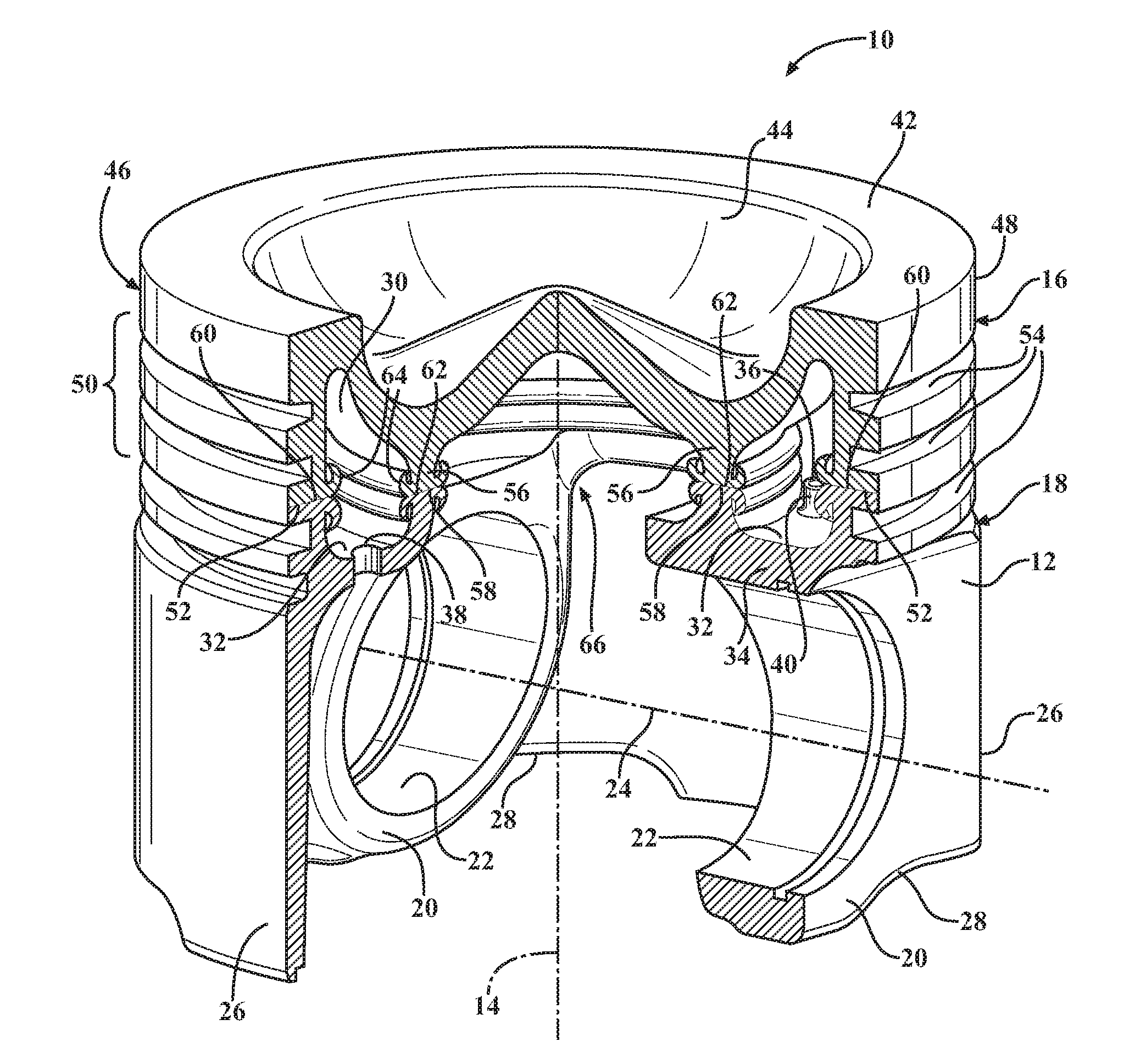
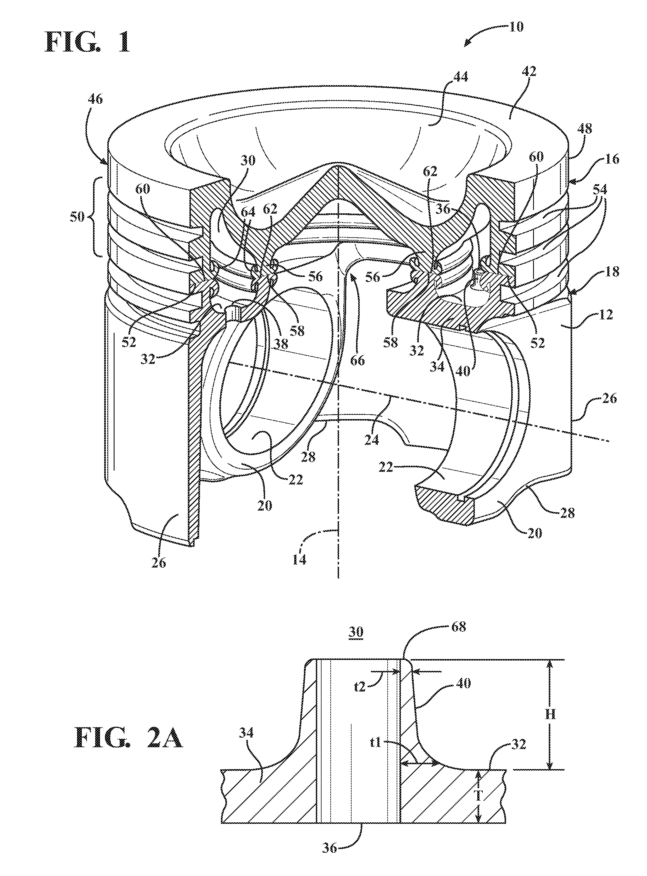
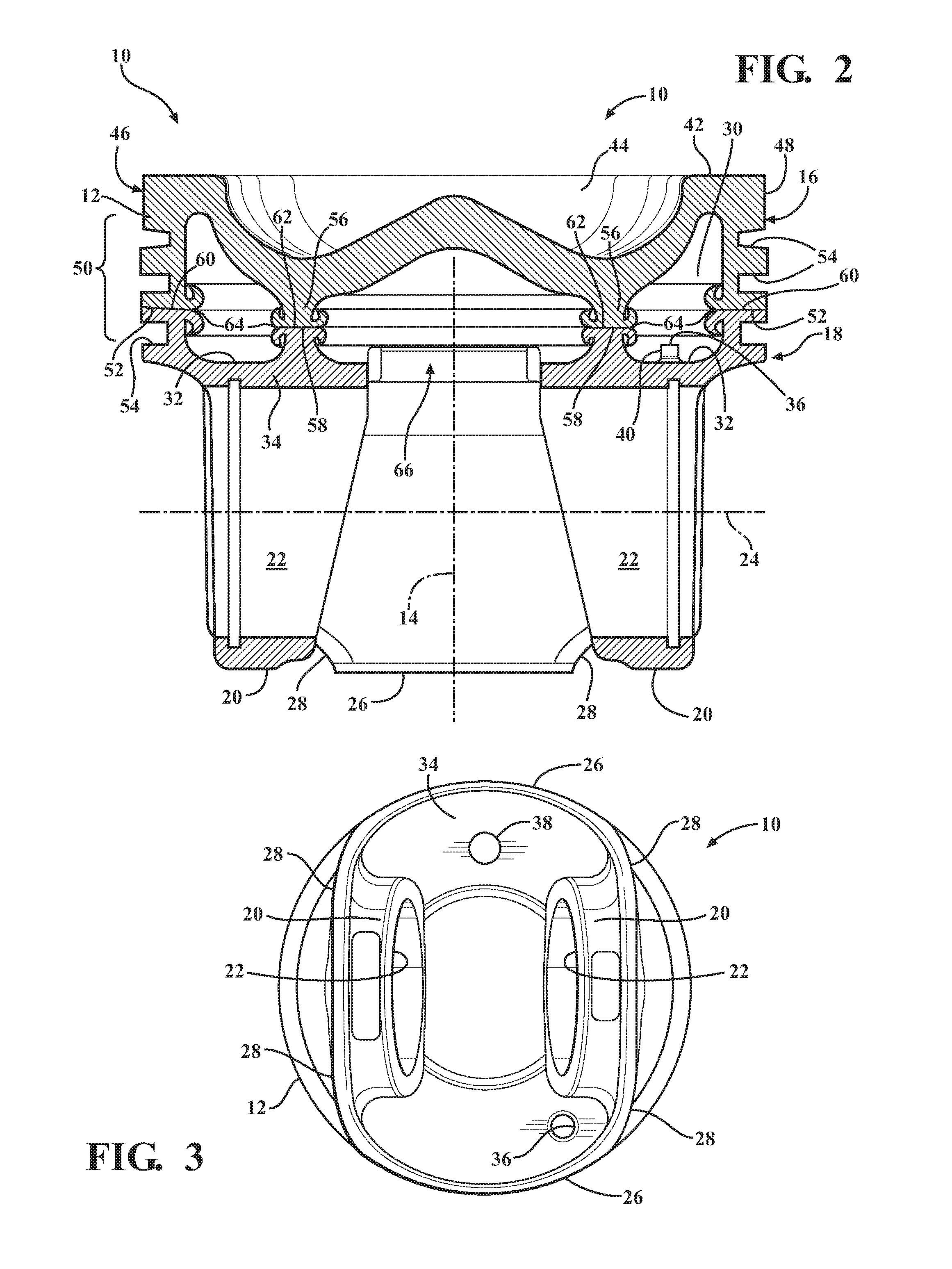
[0023]Referring in more detail to the drawings, FIGS. 1 and 2 illustrate a piston 10 constructed according to one presently preferred embodiment of the invention for reciprocating movement in a cylinder bore or chamber of an internal combustion engine, such as a heavy duty diesel engine, by way of example and without limitation. The piston 10 has a body 12 extending along a central longitudinal axis 14 along which the piston 10 reciprocates in the cylinder bore. The body 12 has an upper crown 16 and a lower crown 18. The lower crown 18 has a pair of pin bosses 20 depending from the upper crown 16 to provide laterally spaced pin bores 22 aligned with one another along a pin bore axis 24 that extends generally transversely to the central longitudinal axis 14. The pin bosses 20 are joined to laterally spaced, diametrically opposite skirt portions 26 via strut portions 28. A substantially closed, annular outer oil cooling gallery 30 is formed between the upper and lower crowns 16, 18, w...


PUM

PropertyMeasurementUnit
thicknessaaaaaaaaaa
heightaaaaaaaaaa
temperatureaaaaaaaaaa

Abstract

A piston and method of construction thereof are provided. The piston includes an upper crown having an upper combustion surface and a lower crown depending therefrom. The lower crown includes a pair of laterally spaced, axially aligned pin bores configured for receipt of a wrist pin. A substantially closed, annular outer cooling gallery is formed between the upper and lower crowns, wherein a bottom surface of the cooling gallery is formed by a floor of the lower crown. An oil inlet and an oil outlet extend through the floor. The oil inlet includes an upstanding toroid-shaped protrusion that extends upwardly from the floor into the cooling gallery, wherein the protrusion is formed as a monolithic extrusion from the material of the lower crown floor.

Description

CROSS-REFERENCE TO RELATED APPLICATION[0001]This application claims the benefit of U.S. Provisional Application Ser. No. 62 / 094,258, filed Dec. 19, 2014, which is incorporated herein by reference in its entirety.BACKGROUND OF THE INVENTION[0002]1. Technical Field[0003]This invention relates generally to internal combustion engines, and more particularly to pistons and their method of construction.[0004]2. Related Art[0005]Pistons for internal combustion engines are known to include annular cooling galleries to facilitate maintaining the pistons within operable temperature limits. Once oil is delivered into the cooling gallery through an oil inlet, typically located on one side of the piston, it is desirable to have the oil circulate to an opposite side of the piston and exit through an oil outlet, whereupon the oil typically returns to the crankcase. If the oil is allowed to exit the oil inlet, insufficient cooling of the piston can result, thereby potentially diminishing the useful...

Claims


Application Information

Patent Timeline
Patent Type & Authority Applications(United States)
IPC IPC(8): F02F3/22F02F3/00
CPCF02F3/22F02F2200/04F02F2003/0007F02F3/0015B23P15/10F02F3/00F02F3/16F02F3/28F02F2003/0061
Inventor WEINENGER, MICHAEL
Owner TENNECO
Why Eureka
Try Eureka