Bismuth ferrite thin-film solar cell and method of manufacturing the same

a technology of solar cells and bismuth ferrite, which is applied in the direction of vacuum evaporation coating, chemical coating, liquid/solution decomposition chemical coating, etc., can solve the problems of low closed-circuit current density, limit the application of ferroelectric materials in the photovoltaic field, and not all types of element doping can enhance the photoelectric conversion efficiency, so as to reduce the quantity of fe2+ defects, enhance the effect of photoelectric conversion efficiency and reduce the quantity of fe2+

Active Publication Date: 2016-06-23
NAT CHUNG SHAN INST SCI & TECH
View PDF3 Cites 9 Cited by
  • Summary
  • Abstract
  • Description
  • Claims
  • Application Information

AI Technical Summary

Benefits of technology

[0004]In view of the aforesaid drawbacks of the prior art, it is an objective of the present invention to provide a bismuth ferrite thin-film solar cell and a method of manufacturing the same, characterized in that the quantity of Fe2+ defects in the bismuth ferrite thin-film is controlled by zinc doping. The reduction of the quantity of Fe2+ defects in the bismuth ferrite thin-film is conducive to the increase of closed-circuit current density and enhancement of photoelectric conversion efficiency.

Problems solved by technology

Although the electrical field of a ferroelectric material domain wall is stronger than the electrical field of the p-n depletion region in a conventional silicon-based solar cell, an overly low closed-circuit current density places a limit on the application of a ferroelectric material in the photovoltaic field.
However, not all types of element doping can enhance the photoelectric conversion efficiency, because the type, proportion, and preparation process of the doping element affect the current density and the photoelectric conversion efficiency of the finished products of thin-film solar cells.

Method used


Image

  • Bismuth ferrite thin-film solar cell and method of manufacturing the same
  • Bismuth ferrite thin-film solar cell and method of manufacturing the same
  • Bismuth ferrite thin-film solar cell and method of manufacturing the same

Examples


Embodiment Construction

[0012]The implementation of the present invention is hereunder illustrated with specific embodiments, so that persons skilled in the art can easily gain insight into the other advantages and effects of the present invention by referring to the disclosure contained in this specification.

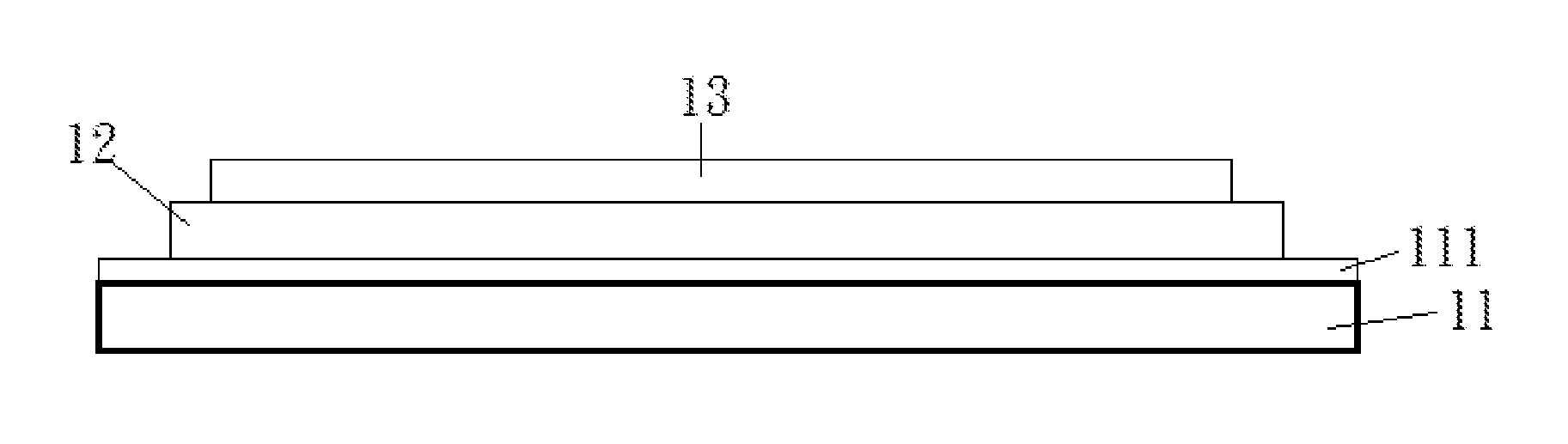
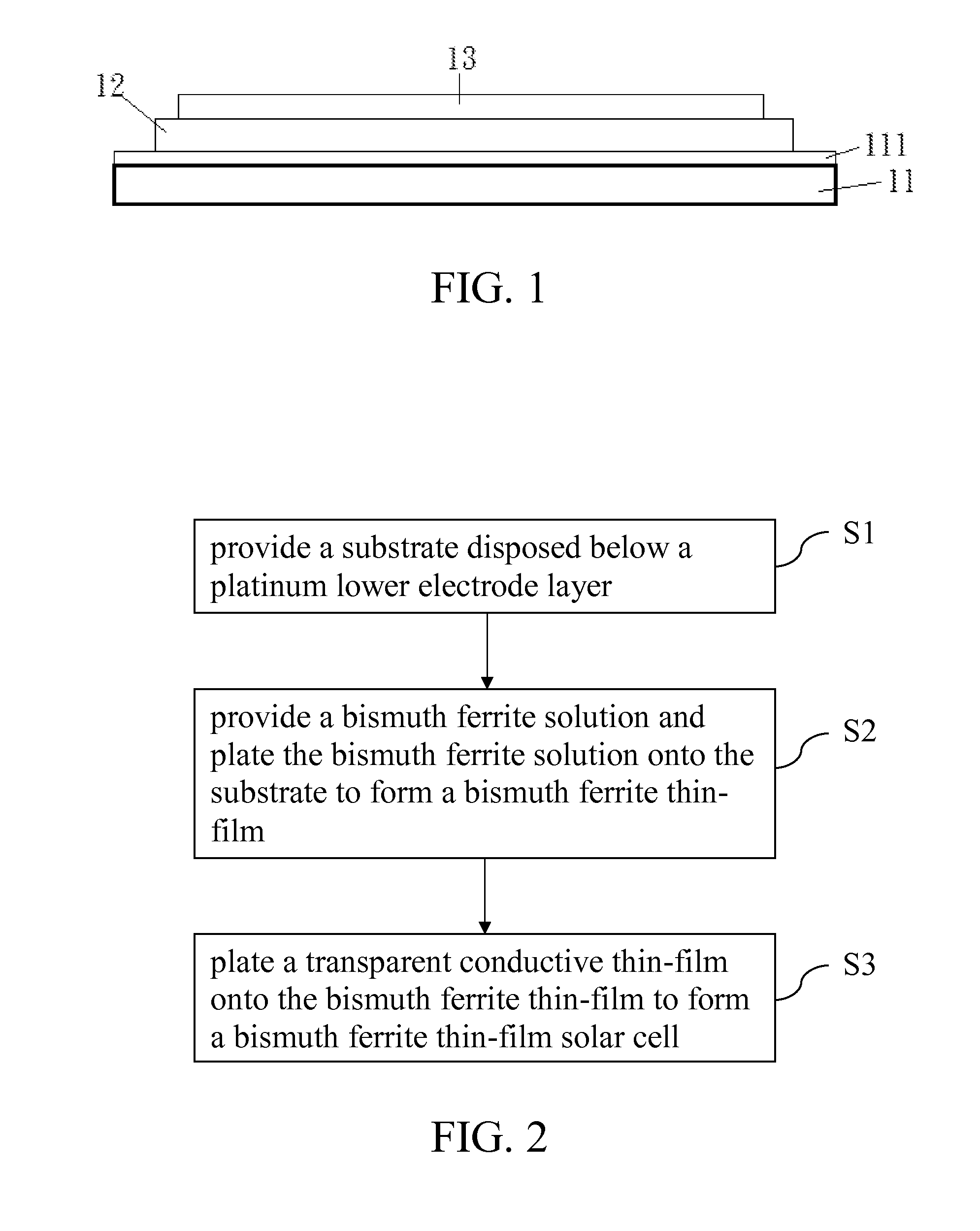
[0013]Referring to FIG. 1, there is shown a schematic view of the structure of a bismuth ferrite thin-film solar cell of the present invention. As shown in the diagram, the bismuth ferrite thin-film solar cell comprises: a substrate 11, wherein the substrate 11 is disposed below a platinum lower electrode layer 111; a bismuth ferrite thin-film layer 12 disposed on the platinum lower electrode layer 111; and a transparent conductive thin-film layer 13 disposed on the bismuth ferrite thin-film layer 12, wherein the bismuth ferrite thin-film is doped by zinc, and the chemical formula of the bismuth ferrite thin-film 12 is (Bi1-xZnx)FeO3-0.5x, where x is no larger than 0.1. The substrate is made of silico...


PUM

PropertyMeasurementUnit
transparent conductiveaaaaaaaaaa
chemicalaaaaaaaaaa
electrical fieldaaaaaaaaaa

Abstract

A bismuth ferrite thin-film solar cell and a method of manufacturing the same control the quantity of Fe2+ defected in the bismuth ferrite thin-film by doping with zinc. Reduction of the quantity of Fe2+ defects in the bismuth ferrite thin-film is conducive to the increase of closed-circuit current density and enhancement of photoelectric conversion efficiency.

Description

FIELD OF TECHNOLOGY[0001]The present invention relates to methods of manufacturing thin-film solar cells, and more particularly, to a method of manufacturing a bismuth ferrite thin-film solar cell, characterized in that the quantity of Fe2+ defects of the thin-film per se is reduced by the doping of an appropriate element.BACKGROUND[0002]A conventional ferroelectric thin-film solar cell is characterized in that its active layer is formed from a thin-film which is made of a single ferroelectric material, such that a built-in electrical field contributed by a ferroelectric domain wall is conducive to separation of carriers when irradiated. Although the electrical field of a ferroelectric material domain wall is stronger than the electrical field of the p-n depletion region in a conventional silicon-based solar cell, an overly low closed-circuit current density places a limit on the application of a ferroelectric material in the photovoltaic field.[0003]Bismuth ferrite is a ferroelectr...

Claims


Application Information

Patent Timeline
Patent Type & Authority Applications(United States)
IPC IPC(8): H01L31/032H01L31/18H01L31/0445C23C14/08C23C14/35
CPCH01L31/032C23C14/08H01L31/1884H01L31/0445C23C14/35C23C18/1204C23C18/1254H01L21/02381H01L21/02491H01L21/02565H01L21/02628H01L31/06H01L31/072Y02E10/50C23C18/00
Inventor TSAI, YUEH-HSUANWEI, CHAO-NANBOR, HUI-YUNLIN, CHIA-SHIHNIEH, CUO-YOWU, JENN-MING
Owner NAT CHUNG SHAN INST SCI & TECH
Why Eureka
Try Eureka