Switching power supply circuit

a power supply circuit and power supply circuit technology, applied in the direction of dc-dc conversion, climate sustainability, efficient power electronics conversion, etc., can solve the problems of high frequency current and voltage components, power factor deterioration, current phase may delay with respect to voltage phase, etc., to improve unstable operation, control during light load can be made stable, and the slope of the sawtooth wave signal can be steep

Active Publication Date: 2016-06-23
FUJI ELECTRIC CO LTD
View PDF4 Cites 17 Cited by
  • Summary
  • Abstract
  • Description
  • Claims
  • Application Information

AI Technical Summary

Benefits of technology

[0035]According to such a switching power supply circuit, the charging current changing circuit makes change to increase the charging current of the sawtooth wave signal of the oscillator in proportion to the decrease of an error amplification signal so that the slope of the sawtooth wave signal can be made steep. Thus, the error signal can be kept at a high voltage in the range in which the error amplification signal decreases so that control during a light load can be made stable.
[0036]In the switching power supply circuit having the aforementioned configuration, the oscillator has the charging current changing circuit. Accordingly, there is an advant...

Problems solved by technology

Therefore, there is a problem that high frequency current and voltage components occur as high frequency noise sources and a power factor deteriorates.
However, in a switching power supply, a current phase may delay with respect to a voltage phase due to another load factor than the resistance load.
Thus, a part of the effective power may lack correspondingly to the delay.
That is, the error signal Verr becomes high in the case where the load is heavy, and becomes low in the case w...

Method used


Image

  • Switching power supply circuit
  • Switching power supply circuit
  • Switching power supply circuit

Examples


first embodiment

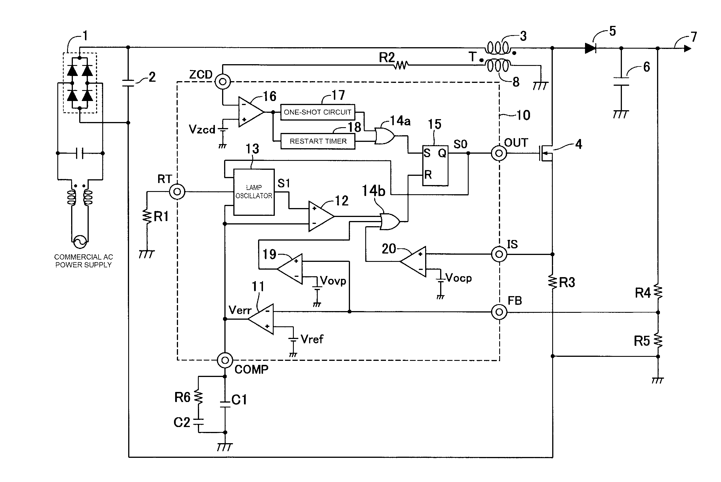
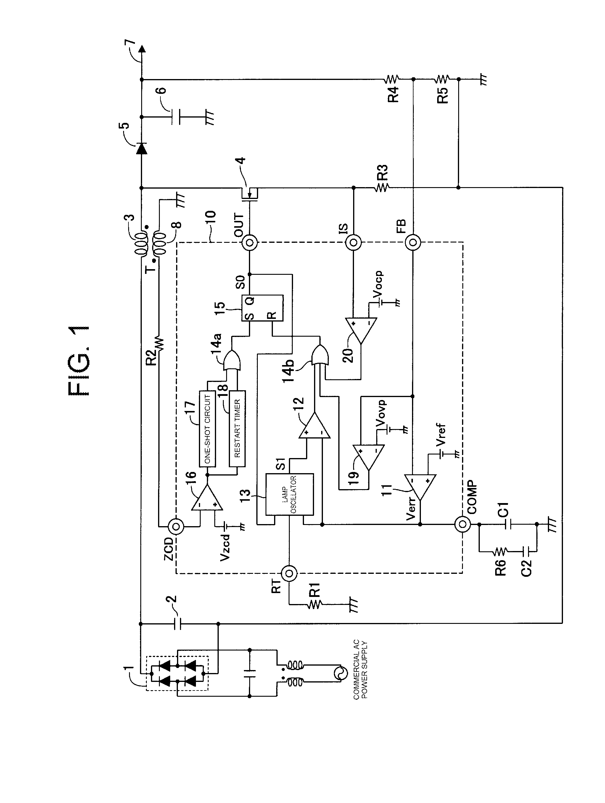
[0054]FIG. 1 is a circuit diagram showing a switching power supply circuit according to the invention. FIG. 2 is a circuit diagram showing a configuration example of a lamp oscillator of the switching power supply circuit according to a FIG. 3 is a graph showing a characteristic of a charging current changing circuit of the lamp oscillator. FIG. 4 is a view for explaining the change of a sawtooth wave signal caused by the change of a load. FIG. 5 is a view for explaining the influence caused by the change of an error signal during a light load. Incidentally, the same symbols will be used hereinafter for constituent elements, terminal names, signal names, etc. corresponding to those of the background-art circuit shown in FIG. 9 respectively, and duplicate description thereof will be omitted.

[0055]In the switching power supply circuit according to the invention, a power factor controller circuit 10 is different from the power factor controller circuit 100 of the switching power suppl...

second embodiment

[0062]FIG. 6 is a circuit diagram showing a configuration example of a lamp oscillator of the switching power supply circuit according to a FIG. 7 is a graph showing a characteristic of a charging current changing circuit of the lamp oscillator.

[0063]As shown in FIG. 6, in the lamp oscillator 13 of the switching power supply circuit according to the second embodiment, the reference voltage 1302 in the circuit according to the background-art example shown in FIG. 10 is replaced by a second charging current changing circuit 30a. Further, a constant current source 1311 connected in parallel with an MOSFET 1305 is added in the lamp oscillator 13.

[0064]The second charging current changing circuit 30a has an operational amplifier 3003, a reference voltage source 3004 and resistors 3005 and 3006, which form an inverting amplifier circuit. That is, a reference voltage 3004 is supplied to a non-inverting input of the operational amplifier 3003. An error signal Verr is supplied to an inverti...


PUM


Abstract

A lamp oscillator which outputs a sawtooth wave signal to be compared with an error signal of an output voltage in order to generate a PWM signal. The oscillator includes a first charging current changing circuit, in which a current amplifier converts a differential voltage between the error signal and a reference voltage into a current and outputs the converted current. When the load of a switching power supply circuit is heavy, a capacitor is charged with a constant current and generates a sawtooth wave signal having a predetermined slope. During a light load, the first charging current changing circuit adds the current, which increases as the load becomes lighter, to the current to thereby make the slope of the sawtooth wave signal steeper.

Description

CROSS-REFERENCE TO RELATED APPLICATIONS[0001]This application claims the priority, under 35 U.S.C. 119, of corresponding Japanese Patent Application No. JP PA 2014-257266, filed Dec. 19, 2014, the entire content of which is hereby incorporated by reference.BACKGROUND OF THE INVENTION[0002]1. Field of the Invention[0003]The present invention relates to a switching power supply circuit. Particularly, it relates to a switching power supply circuit provided with a power factor controller circuit which can stably control switching operation within a wide input voltage range.[0004]2. Description of the Background Art[0005]In lots of electronic devices supplied with commercial alternating current (AC) power supplies (in the range of from AC 100 V to 240 V), switching power supply circuits are used in order to obtain direct current (DC) power supplies driving internal electronic circuits. Therefore, a rectifier circuit for converting a commercial AC power supply into a direct current is req...

Claims


Application Information

Patent Timeline
IPC IPC(8): H02M7/06H02M1/42
CPCH02M1/4208H02M7/06H02M3/156H02M1/4225Y02B70/10H02M1/0032H02M3/158H02M3/1588
Inventor SUGAWARA, TAKATO
Owner FUJI ELECTRIC CO LTD
Why Eureka
Try Eureka