Vehicle engine exhaust system

a technology for exhaust systems and vehicles, which is applied in the direction of machines/engines, mechanical equipment, transportation and packaging, etc., can solve the problems that the charge in a vehicle affects the driving of the vehicle, and the effect of engine power is improved, engine power is increased, and engine power is increased

Active Publication Date: 2016-06-30
TOYOTA JIDOSHA KK
View PDF5 Cites 15 Cited by
  • Summary
  • Abstract
  • Description
  • Claims
  • Application Information

AI Technical Summary

Benefits of technology

[0007]The invention provides a vehicle engine exhaust system that performs static electricity elimination (the static electricity reduction) for an exhaust component, thereby increasing engine power and also improving driving stability of the vehicle.
[0008]An aspect of the invention relates to a vehicle engine exhaust system including an exhaust component and a non-conductive support member. The exhaust component is supported by a vehicle body via the non-conductive support member. The vehicle body and the exhaust component are positively charged. The vehicle engine exhaust system further includes a self discharge type static electricity eliminator that reduces, in a state where the self discharge type static e

Problems solved by technology

However, specifically why and how the static electricity charged

Method used


Image

  • Vehicle engine exhaust system
  • Vehicle engine exhaust system
  • Vehicle engine exhaust system

Examples


Embodiment Construction

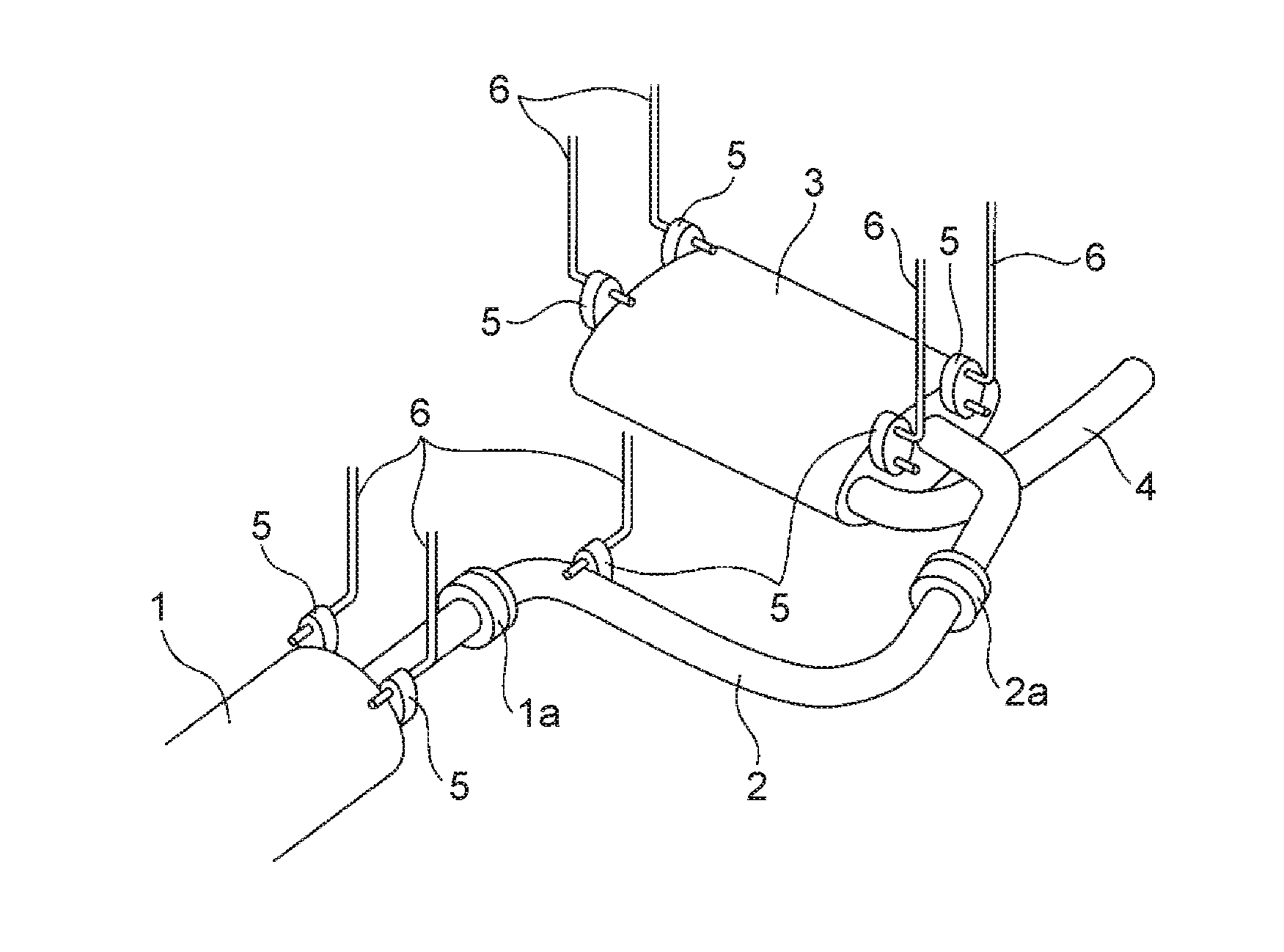
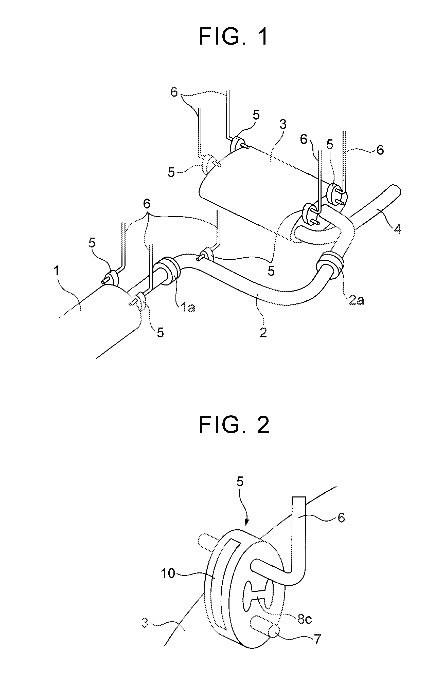
[0020]FIG. 1 shows a perspective view of an engine exhaust system arranged under a vehicle floor. FIG. 1 shows a catalytic converter 1, an exhaust pipe 2 connected to the catalytic converter 1, a silencer 3 connected to the exhaust pipe 2 via a connection part 2a, and a tail pipe 4. In the example shown in FIG. 1, exhaust gas discharged from an engine (internal combustion engine) is sent into the catalytic converter 1, and then the exhaust gas passes through the exhaust pipe 2 and is sent into the silencer 3. Thereafter, the exhaust gas is discharged into the atmosphere from the tail pipe 4. The catalytic converter 1, the exhaust pipe 2, the silencer 3, and the tail pipe 4 are herein referred to as exhaust components. Although not shown in FIG. 1, other components such as an exhaust treatment device and a heat recovery device, which are arranged under the vehicle floor, are also included in the exhaust components.

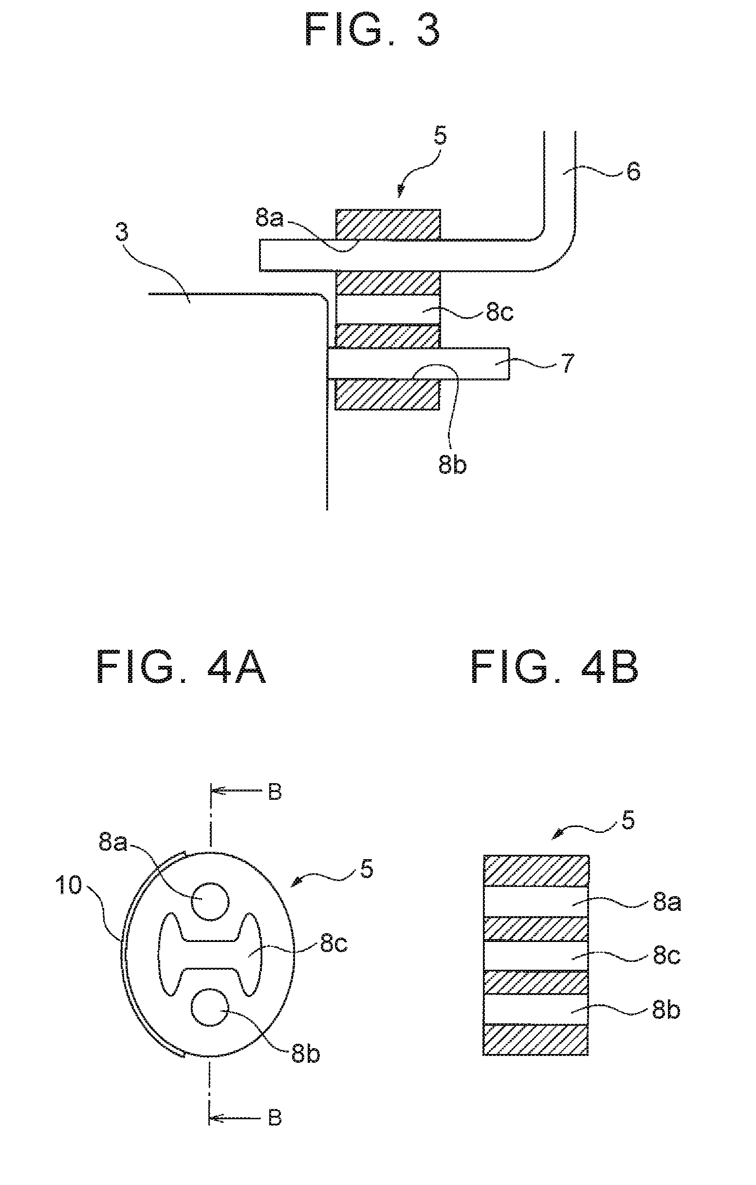
[0021]The exhaust components are supported by a vehicle body via non-c...


PUM

PropertyMeasurementUnit
Electrical conductoraaaaaaaaaa

Abstract

A vehicle engine exhaust system includes an exhaust component and a non-conductive support member. The exhaust component is supported by a vehicle body via the non-conductive support member. The vehicle body and the exhaust component are positively charged. The vehicle engine exhaust system further includes a self discharge type static electricity eliminator that reduces, in a state where the self discharge type static electricity eliminator is installed on a non-conductive wall surface, an amount of electrification charge on the non-conductive wall surface within a limited area around a location where the self discharge type static electricity eliminator is installed. The self discharge type static electricity eliminator is installed on the non-conductive support member such that static electricity elimination is performed for the exhaust component.

Description

INCORPORATION BY REFERENCE[0001]The disclosure of Japanese Patent Application No. 2014-265749 filed on Dec. 26, 2014 including the specification, drawings and abstract is incorporated herein by reference in its entirety.BACKGROUND OF THE INVENTION[0002]1. Field of the Invention[0003]The invention relates to a vehicle engine exhaust system.[0004]2. Description of Related Art[0005]A vehicle is publicly known, in which a discharge device such as a discharge antenna is mounted on an engine or an engine-related member of the vehicle, and high-voltage electricity, static electricity and so on generated or charged in the engine area is discharged and emitted outside, thereby improving fuel economy (for example, see Japanese Patent Application Publication No. 5-238438 (JP 5-238438 A)).[0006]As described in JP 5-238438 A, it has been conventionally known that static electricity is charged in a vehicle, and that static electricity charged in a vehicle have some kind of influence on driving of...

Claims


Application Information

Patent Timeline
IPC IPC(8): F01N13/08H05F3/00F01N13/16
CPCF01N13/08H05F3/00F01N13/16F01N13/18F01N13/1805F01N2240/04F01N13/1822F01N2530/20F01N2530/22B60R16/06B60K13/04
Inventor TANAHASHI, TOSHIOKANEHARA, YOJIYAMADA, KOSHI
Owner TOYOTA JIDOSHA KK
Why Eureka
Try Eureka